Air Collecting Device And Exhaust Air Box, In Particular Usable In Said Device

a technology of air collecting device and exhaust air box, which is applied in the direction of dirt cleaning, combustion treatment, domestic heating details, etc., can solve the problems of not being easily possible, and achieve the effects of facilitating considerably the cleaning of the channel system, considerable freedom, and longer internal tim

Inactive Publication Date: 2008-08-28
MAX MAIER
View PDF68 Cites 38 Cited by
  • Summary
  • Abstract
  • Description
  • Claims
  • Application Information

AI Technical Summary

Benefits of technology

[0035]If, in a further embodiment of the air collecting device according to the invention, the pre-filter in the channel system is arranged immediately next to the suction opening, then the selection of a suitable pre-filter serves to easily accomplish that the entire channel system in the interior remains free from particles and, in particular, free from fat. This facilitates considerably the cleaning of the channel system and allows a cleaning at longer time internals

Problems solved by technology

The unavoidable result is that the value of the mean air velocity at the outlet air opening located near floor level is substantially higher than the above-mentioned value of 0.6

Method used


Image

  • Air Collecting Device And Exhaust Air Box, In Particular Usable In Said Device
  • Air Collecting Device And Exhaust Air Box, In Particular Usable In Said Device
  • Air Collecting Device And Exhaust Air Box, In Particular Usable In Said Device

Examples


first embodiment

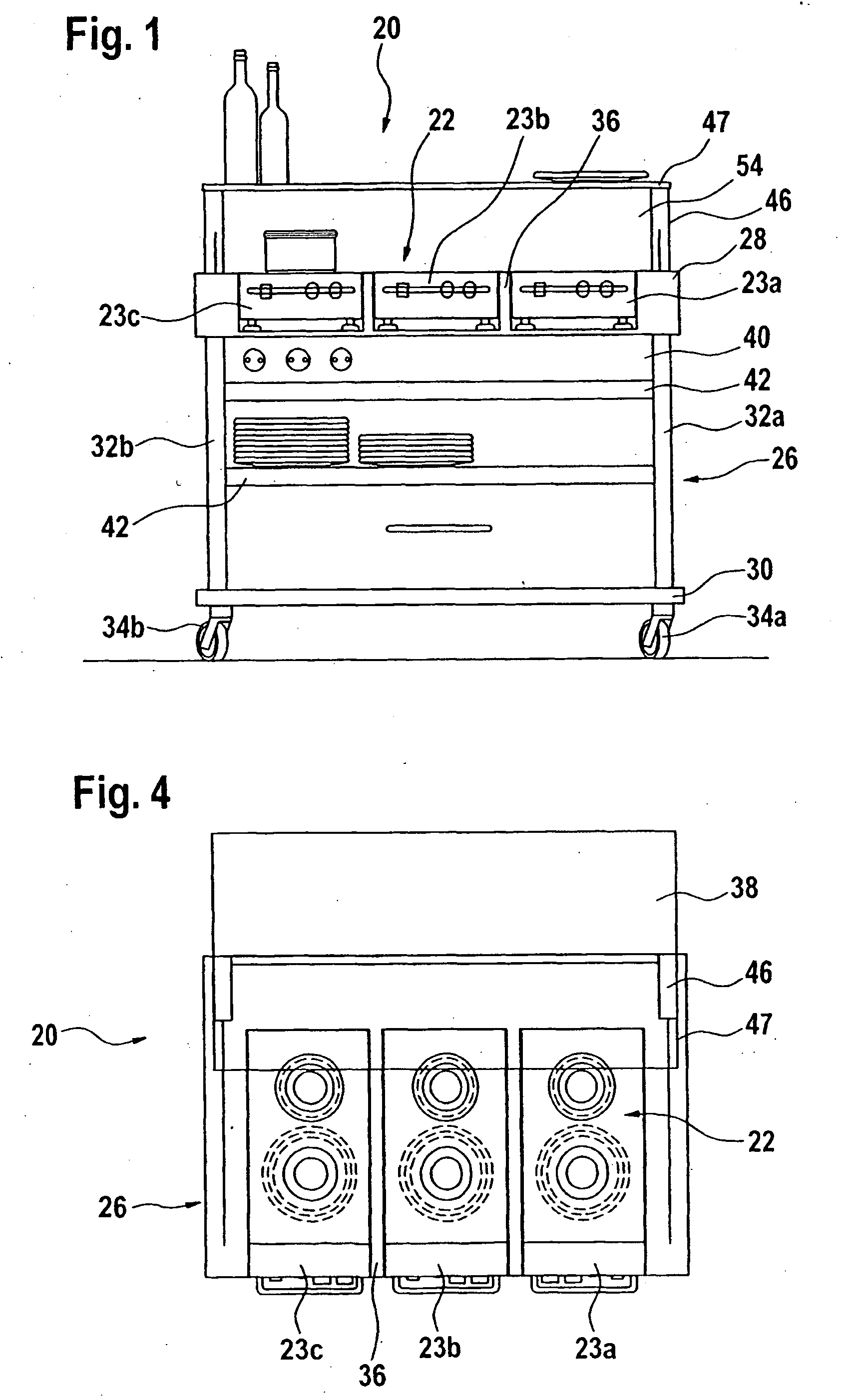
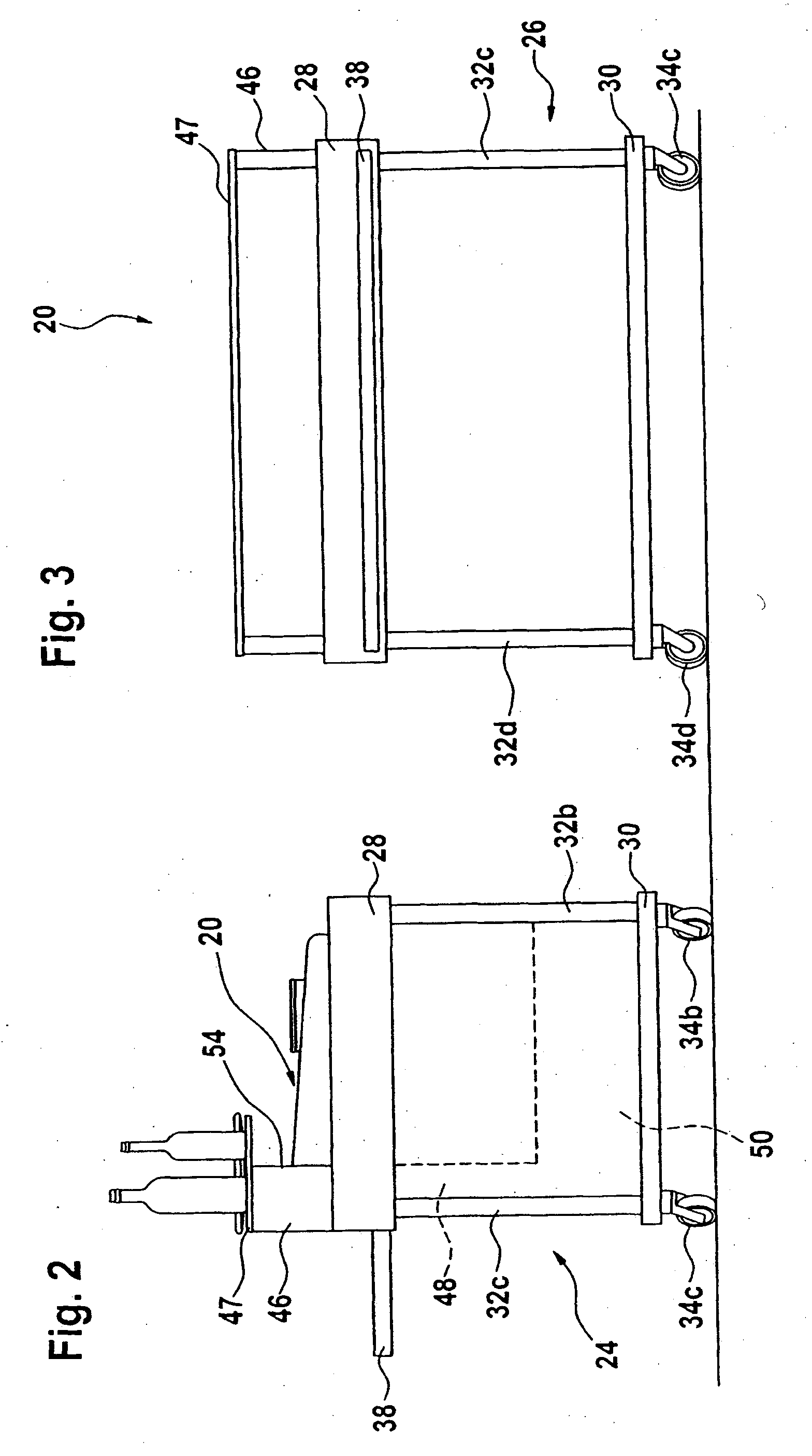
[0065]FIGS. 1-4 show a mobile food distribution equipment, generally designated 20, with a food cooking apparatus, generally designated 22, and with a vapour collecting device, generally designated 24, according to the invention, in rear view, side view, front view and top view, respectively. The mobile food distribution equipment 20 is accommodated on a trolley 26 which has an upper frame 28 and a lower frame 30 which are connected up together by means of four vertical columns 32a-32d, and supported on the floor by means of four caster wheels 34a-34d. In the upper frame 28 a niche 36 is formed which, as shown in FIG. 1, is open on the rear side of the trolley 26. The food cooking apparatus 22 is located in the niche 36 and consists of three thermal devices 23a-23c arranged next to one another for keeping food warm and / or for cooking the food. According to the illustration in the FIGS. 2-4, the food distribution equipment 20 has a tray slide 38 on its front or customers side, and th...

fourth embodiment

[0077]FIG. 11 is a perspective and schematic illustration of the vapour collecting device 24 according to the invention which is suitable for use in a kitchen or in a food distribution equipment. The fat filter 60 is integrated in the scoop 46. The fan 52, which is combined with the exhaust air box 50, is accommodated in a fan chamber 51 attached to the exhaust air box 50 or partitioned off from the exhaust air box 50. The scoop 46 and the fan chamber 51 are connected by means of an inlet air channel 48′ which is formed by a flexible hose. Only one lateral surface of the exhaust air box 50 is shown, namely the bottom or lower surface provided with an outlet air opening 56a and an odour filter 62a. However, the vertical lateral surfaces of the exhaust air box and the flap 66 can each be equipped with an outlet air opening and an odour filter, except for the lateral surface which has the air inflow opening 64.

[0078]In the very simplified illustration in FIG. 11 the air outlet channel,...

fifth embodiment

[0079]The FIGS. 12 and 13 show as a detail the vapour collecting device 24, according to the invention, a cylinder-shaped exhaust air box 50′ of same in side view and in a partial longitudinal sectional view, respectively. The fan 52 is arranged in a lower chamber or fan chamber 51′ of the exhaust air box 50′. The exhaust air box 50′ is connected to the remaining channel system, not shown in the FIGS. 12 and 13, by way of the fan 52 in the fan chamber 51′ and an inlet air channel 48′ which is formed as a flexible hose and connected to the fan chamber 51′. An upper chamber 78 is formed on its entire shell surface as a grid-screened outlet air opening 80 which is covered off on the inner side of the grid 57 with an odour filter 62. The upper chamber 78 is closed off with a removable cover or flap 82, both of which can be locked in the shut position.

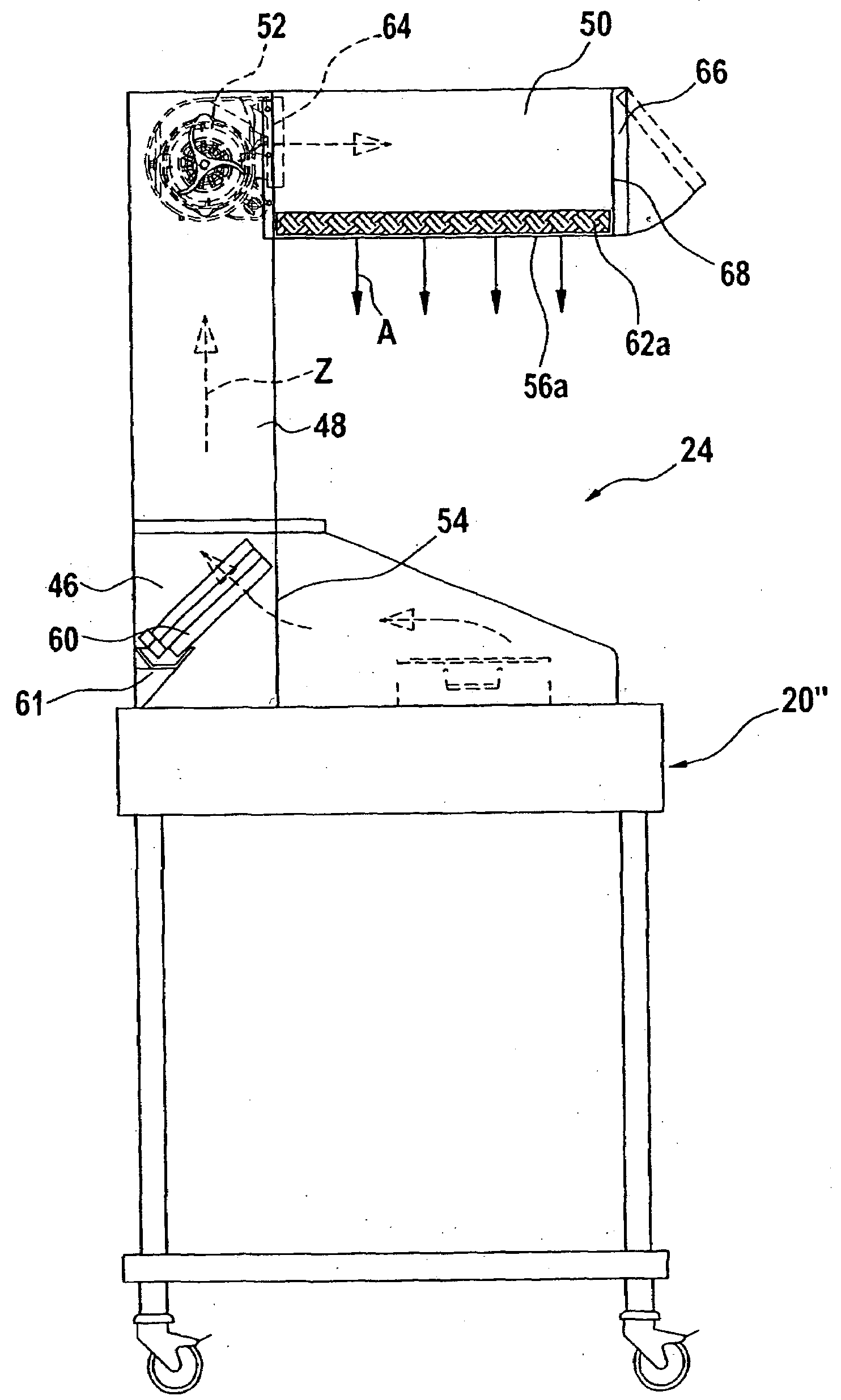
[0080]FIG. 14 shows in side view and partially in section a mobile food distribution equipment, generally designated 20″, with a food cook...


PUM

PropertyMeasurementUnit
Thicknessaaaaaaaaaa
Electrical resistanceaaaaaaaaaa
Flexibilityaaaaaaaaaa

Abstract

The invention relates to an air holding device comprising a channel system raised from a suction opening disposed at a height of a workstation generating dirty air or vapours and leading to at least one outlet opening. An exhausting fan is placed between a prefilter and at least one odour filter. The channel system is embodied in the form of an exhaust air box disposed downstream of the exhaust fan. The lateral surface of the exhaust air box comprises an air inlet which is connected to the downstream side of the exhausting fan. The other lateral surfaces are selectively provided with air outlet openings covered respectively with an odour filter having an adjustable air resistance. Said odour filter preferably consists of a foam material coated with active carbon and the air resistance thereof is selectable according the thickness and/or porosity of the foam material.

Description

FIELD OF THE INVENTION[0001]The invention relates to an air collecting device and an exhaust air box.BACKGROUND OF THE INVENTION[0002]In principle, such an air collecting device can be installed in all kinds of workstations wherein the air emits odours and, depending on the circumstances, is additionally loaded with fat or particles, for example at workstations in kitchens, food distribution equipment, workshops, laboratories or even anatomic or legal medicine institutes.[0003]An example for a kitchen workstation is a food cooking apparatus as known from EP 0 915 299 B1 which is provided with such an air collecting device designed as a vapour collecting device and which is integrated in a cooking and sales counter, and is described further down below in greater detail.[0004]According to an “Instruction Leaflet for large-scale kitchen equipment with an integrated vapour collecting device that is not connected to the ventilation and air conditioning system”, listed as No. F5-2N056, pu...

Claims


Application Information

Patent Timeline
IPC IPC(8): F24C15/20B01D53/22F24F7/00
CPCF24C15/2042B01D46/0002F24C15/2035
Inventor EBERHARD, JURGEN
Owner MAX MAIER
Why Eureka
Try Eureka