Portable safety ladder assembly

a safety ladder and assembly technology, applied in the field of safety ladder assembly, can solve the problems of affecting the safety of workers, and affecting the safety of workers, and achieve the effect of safe and rapid installation

Inactive Publication Date: 2008-08-28
ANDERSON JAMES T +1
View PDF10 Cites 28 Cited by
  • Summary
  • Abstract
  • Description
  • Claims
  • Application Information

AI Technical Summary

Benefits of technology

[0014]In view of the foregoing, it is an object of the present invention to provide a portable safety ladder assembly and a safety extension which permits a

Problems solved by technology

Occupational injuries resulting from ladder falls are a known hazard, especially for vehicles having flatbeds such as dock-height and drop-deck flatbed trailers and railcars, especially (but not limited to) those with head racks.
Such falls result as the operator and/or driver is attempting to ascend or descend the flatbed, therein resulting in a disabling injury or even death.
Moreover, access to the working surface of the flatbed poses significant risk of falling to the ground without a firmly installed flatbed ladder.
Previously, access by ICC rail, a wheel rim or from cab to trailer transfer to access a flatbed having a height of approximately five feet or alternatively using a step ladder which can easily tip over and is unstable.
This method, however, still places the driver and/or operator at risk when ascending up or descending down the ladder (again, especially when the trailer has a head rack that must be climbed around).
Furthermore, since tractors and trailers are sometimes interchangeable, operators will not always have the aforementioned steps available to them (even owner-operators who may be forced to use a rental tractor at times).
Often times, however, such portable step ladders are not utilized due to the inconvenience of deploying them when needed.
Moreover, the base or feet of such prior art ladders are unstable, in particular, they are prone to inadvertent displacement or shifting from the support area on the ground surface when a user is ascending up or descending down the ladder.
The base is also susceptible to slipping in hazardous surface conditions such as rain, snow, ice, etc., and thus, causes the ladder to move and/or topple over.
This manner, however, is extremely dangerous, especially when hazardous weather conditions such as rain, snow, ice, etc., are present.
The aforementioned design, however, has serious ergonomic drawbacks that lack adequate safety protocols to the user.
For inst

Method used


Image

  • Portable safety ladder assembly
  • Portable safety ladder assembly
  • Portable safety ladder assembly

Examples


Embodiment Construction

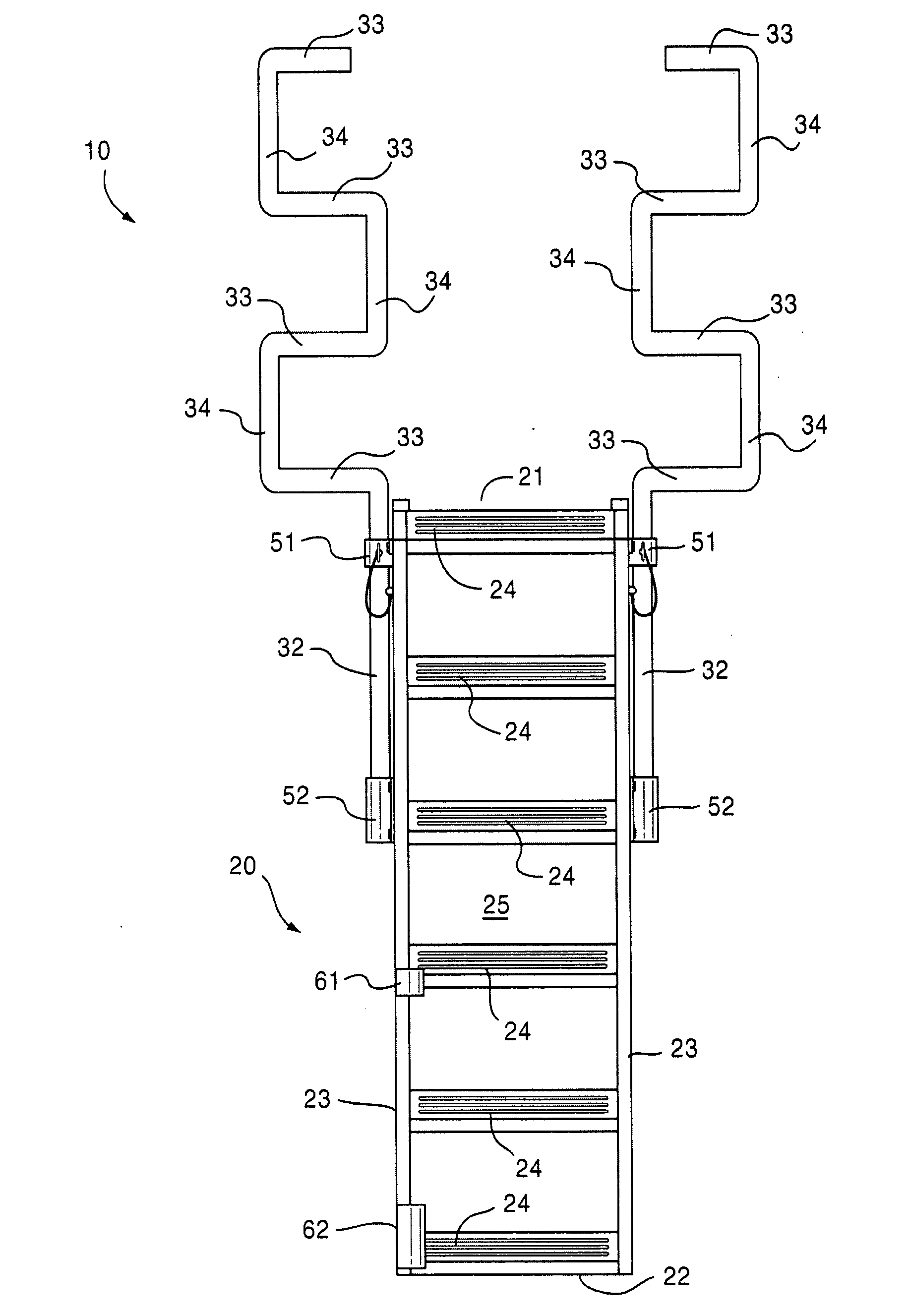
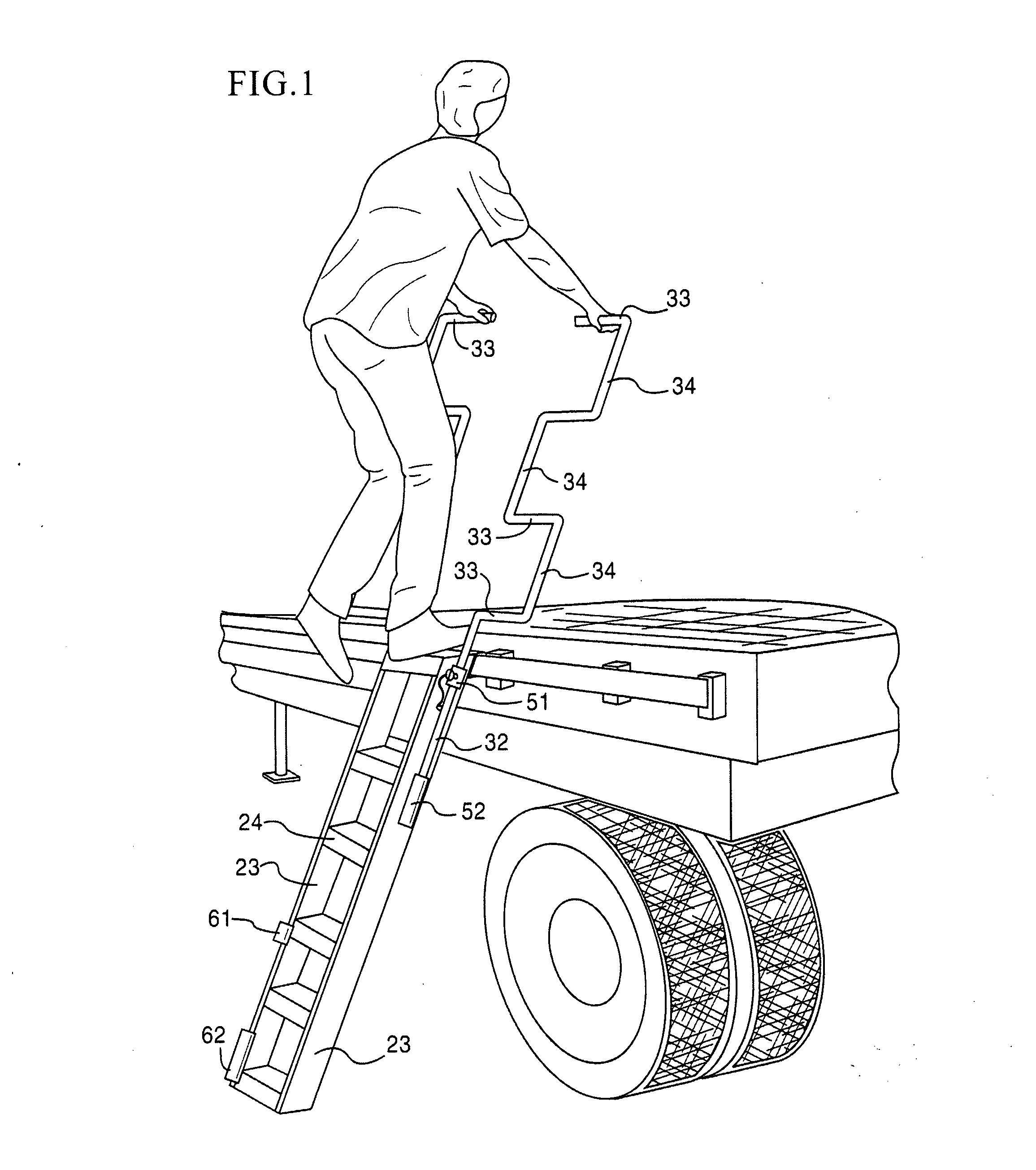
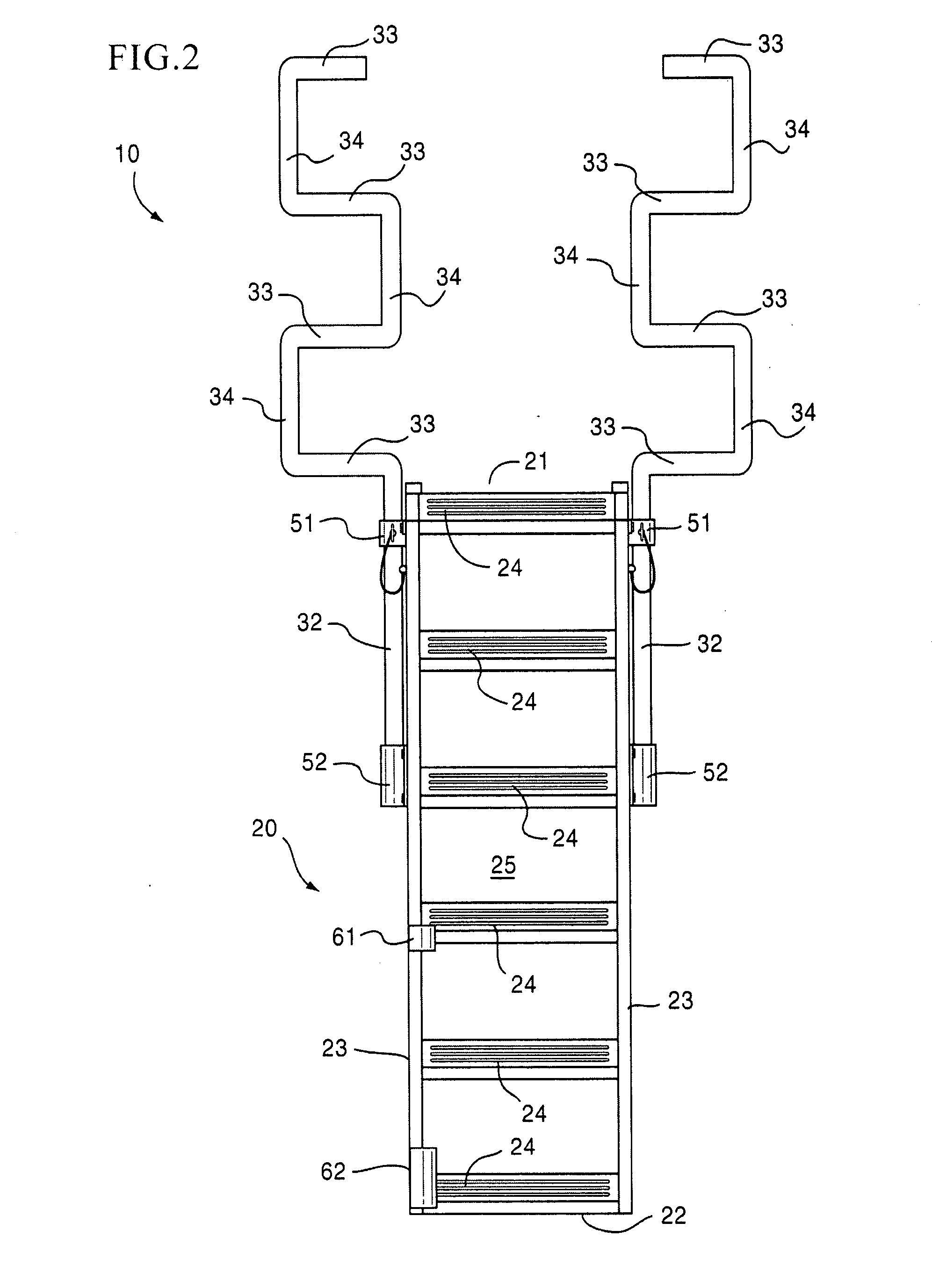
[0046]As illustrated in the drawing figures, provided herein is a portable safety ladder assembly 10 including a ladder 20 and a safety extension 30 for permitting a user to have safe access to a working platform of an intended structure such as a flatbed trailer, rail car and the like. The safety ladder assembly 10 or the safety extension 30 are not limited to use soley with flatbed trailers or railcars and may be used for non-trailer purposes and various applications requiring access to any landing area, working platform, scaffold and the like.

[0047]As shown in FIG. 1, the ladder 20 includes a walk-through section 21 at a distal, uppermost end, a base end 22 which contacts and engages a base surface, e.g., the ground, to provide an area of support for the assembly 10 when placed in an operable position. The ladder 20 also includes a pair of parallel side rails 23 connected by a plurality, i.e., more than two, of horizontal rungs 24, a front section 25 directly facing wherein which...


PUM


Abstract

A safety ladder assembly and a safety extension used in combination with a ladder suitable to permit safe and easy access to the landing areas, working platforms, scaffolds, etc. The assembly includes safety extension members having a plurality of horizontal handgrips ergonomically designed to prevent falls from the ladder when a user is ascending upward or descending downward.

Description

BACKGROUND OF THE INVENTION[0001]1. Field of the Invention[0002]A safety ladder assembly and a safety extension used in combination with a ladder suitable to permit safe and easy access to a landing area, working platform or scaffold. Particularly, a portable and stowable safety ladder assembly which provides safe and convenient access to working platforms and includes a pair of safety extension members having horizontal handgrips or grab bars that enable a user to safely walk up or down the ladder.[0003]2. Description of the Related Art[0004]Occupational injuries resulting from ladder falls are a known hazard, especially for vehicles having flatbeds such as dock-height and drop-deck flatbed trailers and railcars, especially (but not limited to) those with head racks. Such falls result as the operator and / or driver is attempting to ascend or descend the flatbed, therein resulting in a disabling injury or even death. The Bureau of Labor Statistics (BLS) records for falls from non-mov...

Claims


Application Information

Patent Timeline
IPC IPC(8): E06C7/18
CPCB60R3/007E04G5/10E06C7/48E06C7/182E06C5/02
Inventor ANDERSON, JAMES T.ELLIS, J. NIGEL
Owner ANDERSON JAMES T
Why Eureka
Try Eureka