
In-vehicle emergency report apparatus

a technology for emergency reports and vehicles, which is applied in the field of vehicle emergency reports, can solve the problems of useless consumption of auxiliary batteries, inability to effectively switch from vehicle batteries to auxiliary batteries, etc., and achieve the effect of preventing the capacity of auxiliary batteries from being uselessly consumed

Active Publication Date: 2008-08-28
HUAWEI TECH CO LTD
View PDF5 Cites 28 Cited by
  • Summary
  • Abstract
  • Description
  • Claims
  • Application Information

AI Technical Summary

Benefits of technology

[0006]The present invention has been made in consideration of the foregoing. An object of the present invention is to provide an in-vehicle emergency report apparatus where the operating power source can be effectively switched from a vehicle battery to an auxiliary battery and the capacity of the auxiliary battery can be prevented from being uselessly consumed.

Problems solved by technology

Therefore, the operating power source cannot be effectively switched from the vehicle battery to the auxiliary battery, and this uselessly consumes the capacity of the auxiliary battery.

Method used


Image

  • In-vehicle emergency report apparatus
  • In-vehicle emergency report apparatus
  • In-vehicle emergency report apparatus

Examples


first embodiment

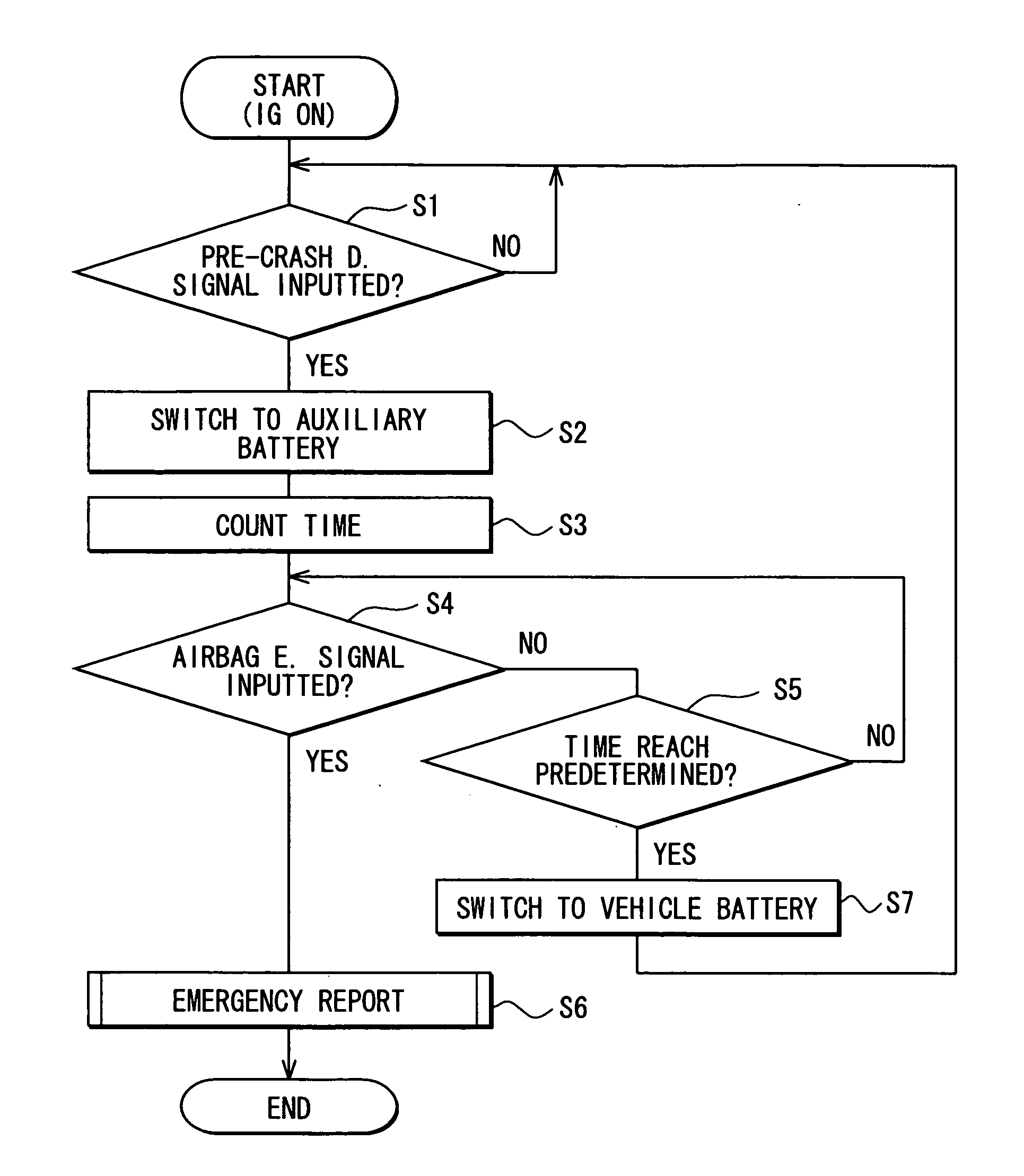
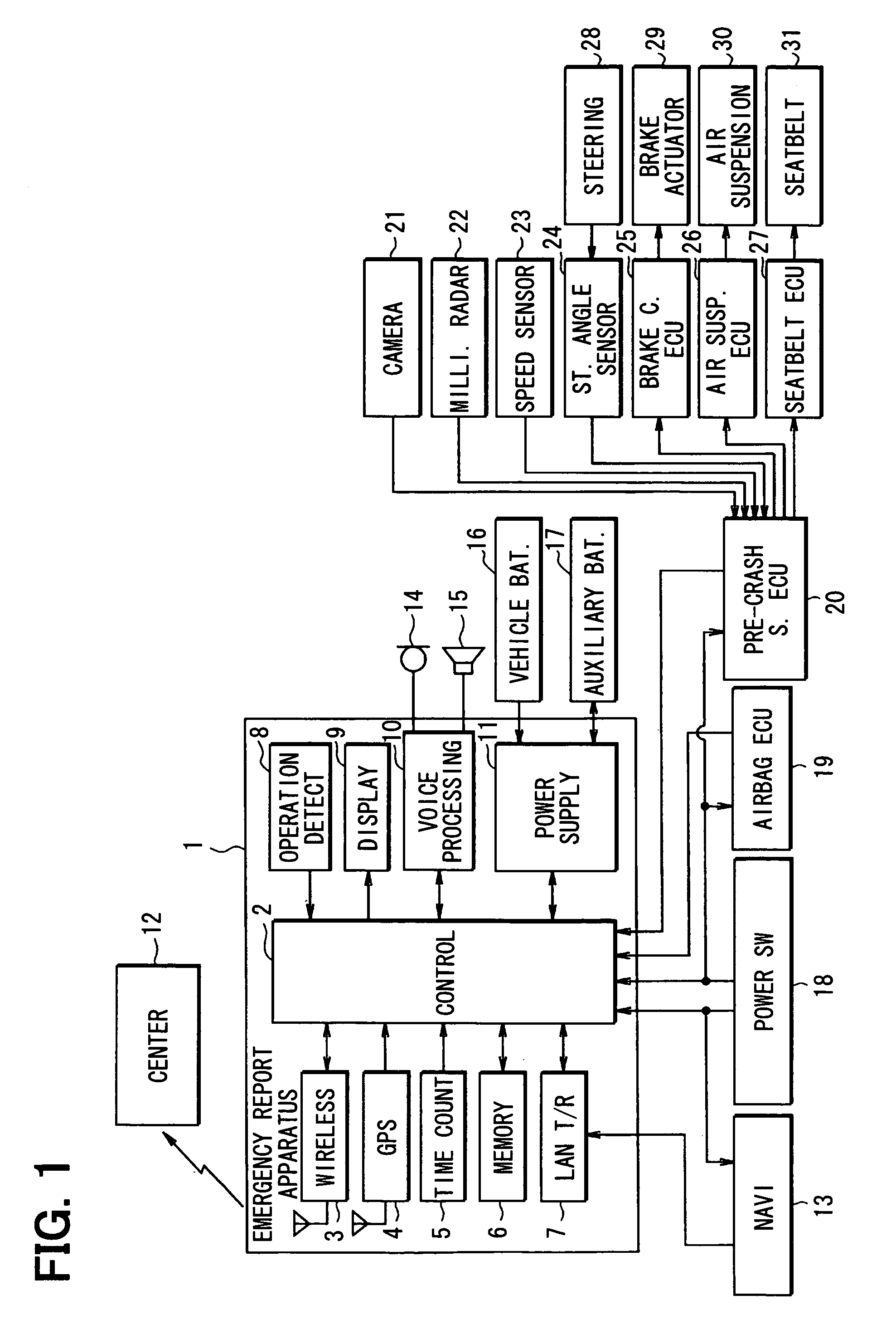
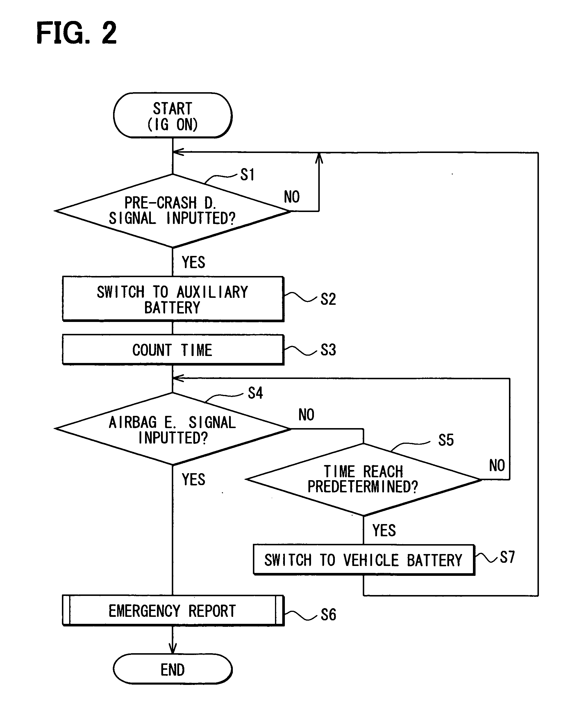
[0013]Hereafter, description will be given to a first embodiment of the present invention with reference to FIG. 1 and FIG. 2. FIG. 1 illustrates the overall configuration of an in-vehicle emergency report apparatus in the form of functional block diagram. The in-vehicle emergency report apparatus 1 is constructed of: a control circuit 2 (functioning as a control means), a wireless communication device 3, a GPS (Global Positioning System) positioning device 4, a time counting device 5 (functioning as a time counting means), a memory device 6, a LAN transmission / reception device 7, an operation detection device 8 (functioning as an operation detecting means), a display device 9, a voice processing device 10, and a power supply device 11 (functioning as a power supplying means).

[0014]The control circuit 2 is constructed based on CPU and controls the overall operation of the in-vehicle emergency report apparatus 1. When the wireless communication device 3 is inputted with an emergency ...

second embodiment

[0028]Description will be given to a second embodiment of the present invention with reference to FIG. 3. The description of the same portions as in the first embodiment will be omitted, and description will be given to a difference. The first embodiment is so constructed that when a pre-crash detection signal is inputted from the pre-crash safety ECU 20, the operating power source is switched from the vehicle battery 16 to the auxiliary battery 17. Meanwhile, the second embodiment is so constructed that when an airbag expansion signal is inputted from the airbag ECU 19, the operating power source is switched from the vehicle battery 16 to the auxiliary battery 17.

[0029]More specific description will be given. The control circuit 2 is so constructed that it can selectively switch the operation mode between normal operation mode and low-power consumption operation mode in which less power is consumed than in normal operation when it operates. (In normal operation mode, operation is p...


PUM


Abstract

An in-vehicle emergency report apparatus is so constructed that the operating power source is switched from a vehicle battery to an auxiliary battery only when a pre-crash safety ECU determines that a vehicle will collide with something. That is, the operating power source is switched from the vehicle battery to the auxiliary battery only when there is a possibility that the vehicle will collide with something to thereby perform emergency report operation. This makes it possible to effectively switch the operating power source from the vehicle battery to the auxiliary battery and to prevent the capacity of the auxiliary battery from being uselessly consumed.

Description

CROSS REFERENCE TO RELATED APPLICATION[0001]This application is based on and incorporates herein by reference Japanese Patent Application No. 2007-47291 filed on Feb. 27, 2007.FIELD OF THE INVENTION[0002]The present invention relates to an in-vehicle emergency report apparatus.BACKGROUND OF THE INVENTION[0003]There are in-vehicle emergency report apparatuses so constructed that emergency report operation can be performed with reliability when a starting trigger for emergency report operation occurs. For this purpose, these in-vehicle emergency report apparatuses are so constructed that the following operation is performed: when the supply voltage of a vehicle battery drops, for example, on starting an engine, the operating power source is switched from the vehicle battery to an auxiliary battery. (Refer to Patent Document 1, for example.)[0004]Patent Document 1: JP 2000-322677 A (corresponding to US2004 / 0075345 A1)[0005]When the operating power source is frequently switched from a v...

Claims


Application Information

Patent Timeline
IPC IPC(8): B60L1/00H02J7/00B60R16/023B60R16/033B60R21/00B60R21/01B60R21/0134B60R21/017G08G1/16
CPCB60R21/0134B60R2021/0027B60R2021/01272B60R2021/01259B60R2021/01088
Inventor KAMIYA, SHINJI
Owner HUAWEI TECH CO LTD
Learn More