Rotation detecting sensor

a technology of rotating detection and sensors, applied in the direction of instruments, measurement device, measurement apparatus components, etc., can solve the problems of reduced detection accuracy, small thickness of resin coating, risk of immersion, etc., and achieve the effect of reducing the overall size and easy sealing

Inactive Publication Date: 2008-08-28
SUMIDEN ELECTRONICS
View PDF4 Cites 44 Cited by
  • Summary
  • Abstract
  • Description
  • Claims
  • Application Information

AI Technical Summary

Benefits of technology

[0025]According to the present invention, a new waterproof structure of a detector is provided in a rotation detecting sensor in which the detector is simply

Problems solved by technology

A portion of the resin coating having a small thickness may have a defect such as a pinhole, and there is a risk of immersion due to such a defect.
In the process of injection molding of the r

Method used


Image

  • Rotation detecting sensor
  • Rotation detecting sensor
  • Rotation detecting sensor

Examples


Embodiment Construction

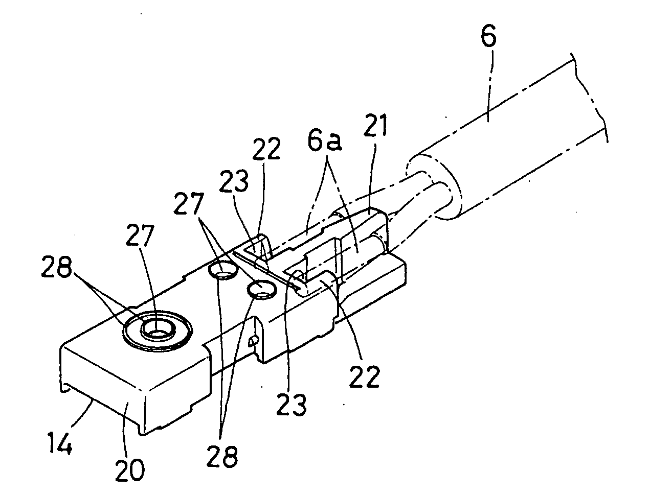
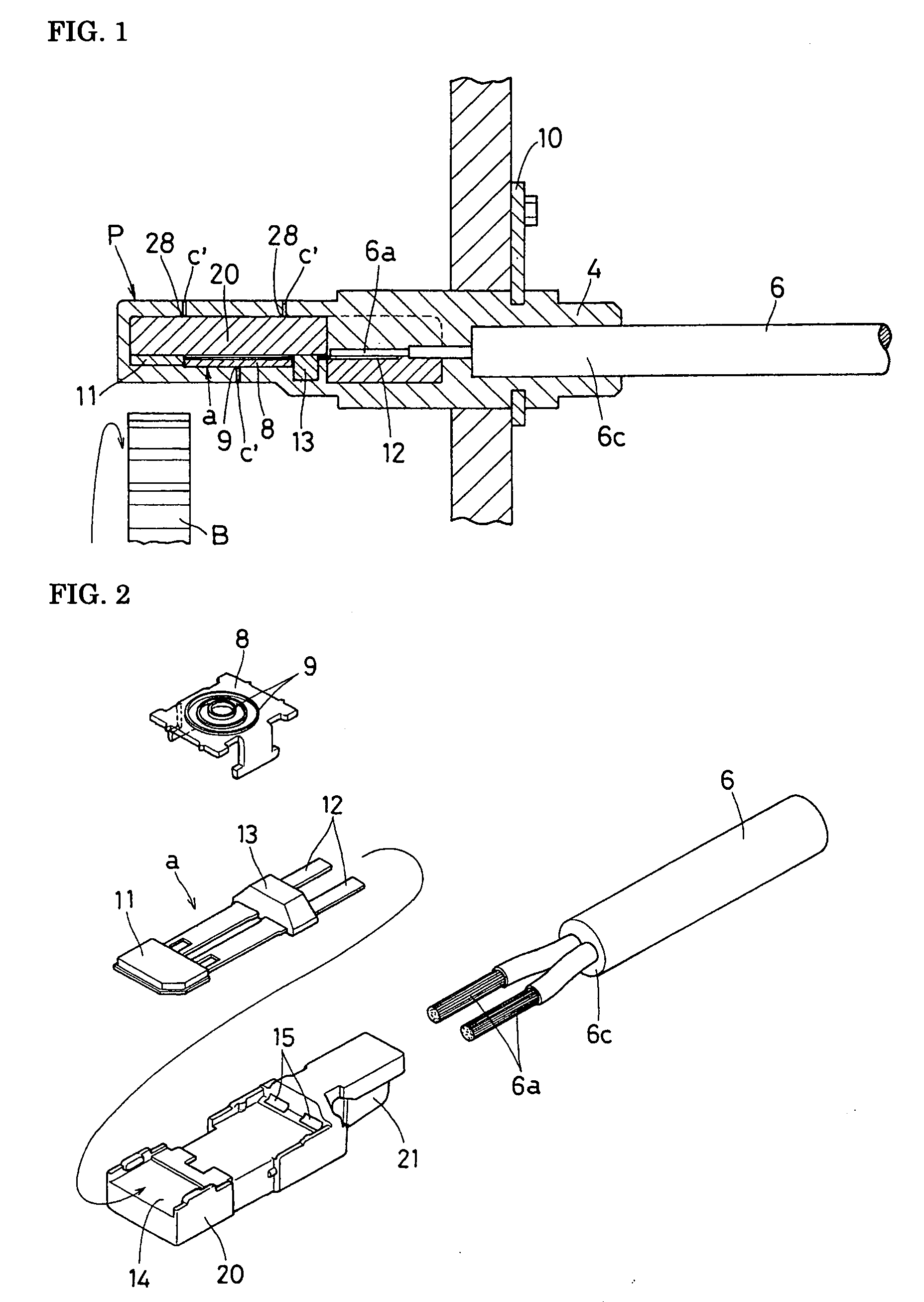
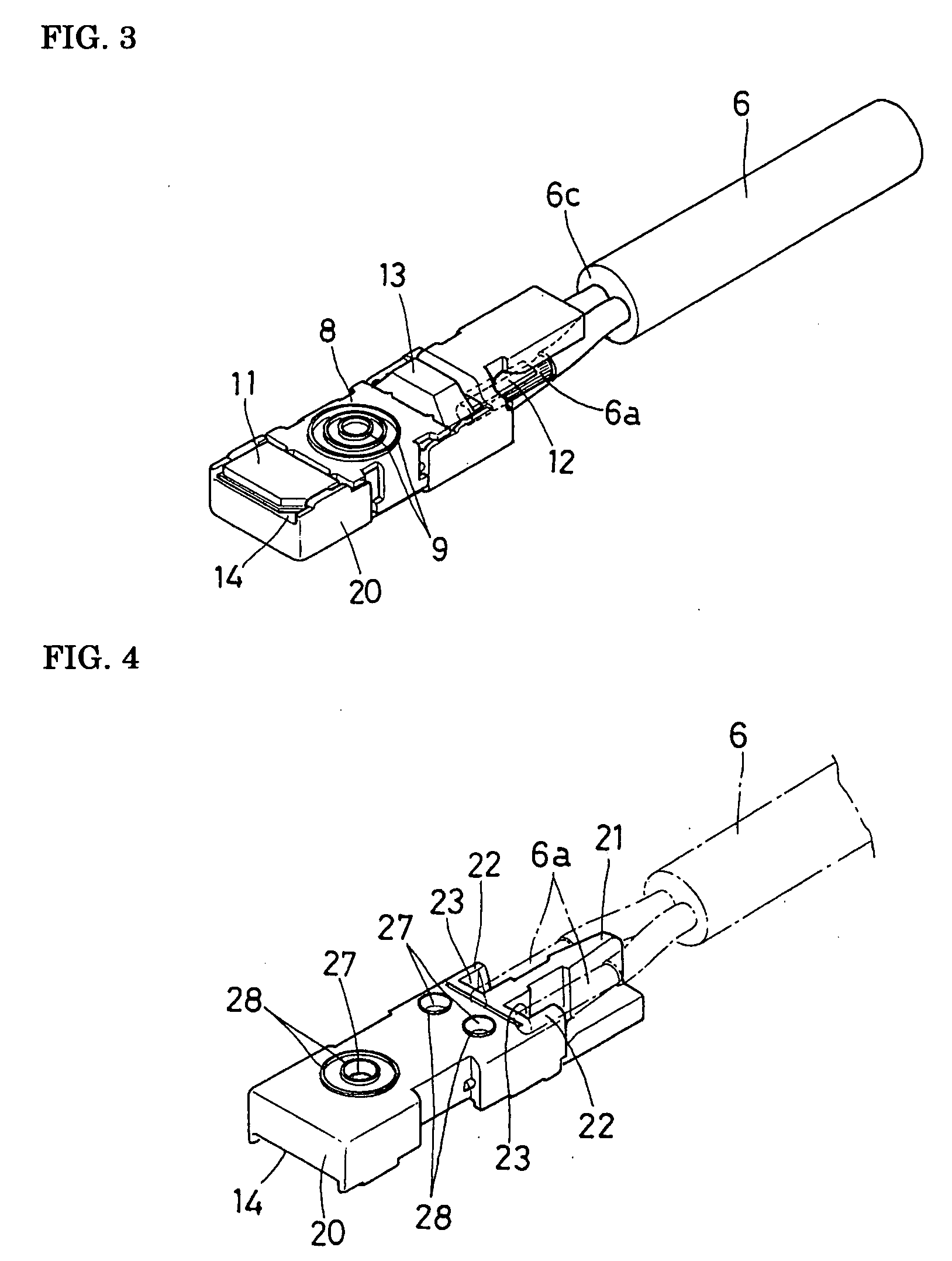
[0038]FIGS. 1 to 4 illustrate an embodiment of the present invention. In this embodiment, a wheel speed sensor P includes a detector a. The detector a includes a hall IC 11 having a hall element (rotation detecting element) that detects a change of magnetic field, a pair of linear lead pieces (lead terminals) 12 extending parallel to each other from the hall IC 11, and an electronic component 13, such as a capacitor, disposed between the lead pieces 12 and 12. The lead pieces 12 and 12 are connected to respective flexible core wires (conductors) 6a and 6a, which are electric insulated wires included in an output cable 6 by soldering or the like (see FIGS. 2 to 4). The electronic component 13 can be omitted as necessary.

[0039]A holder 20 is formed by resin molding. As shown in FIGS. 2 and 3, the holder 20 has a rectangular solid shape and a fitting concave portion 14 for receiving the hall IC 11 is provided on one side of the holder 20 in a front region thereof. In addition, insertio...


PUM

PropertyMeasurementUnit
Lengthaaaaaaaaaa
Magnetic fieldaaaaaaaaaa

Abstract

A wheel speed sensor includes a hall IC that outputs a signal representing a change of magnetic field generated by rotation of a detection object and that is simply covered with resin coating. In the process of molding the resin coating, a resin injection opening is positioned away from an end face of a sheath of a cable to be coated by a length no less than a minimum adhesion length for ensuring adhesion between the sheath and the resin coating. In addition, the holder and a cover of the detector are provided with waterproof protrusions extending along the entire peripheries of contact areas in which pressing pins are brought into contact with the holder and the cover. Accordingly, immersion of the detector is reliably prevented even when a void or the like occurs in the resin coating at a position near the injection opening.

Description

BACKGROUND OF THE INVENTION[0001]1. Field of the Invention[0002]The present invention relates to rotation detecting sensors, such as a wheel speed sensor and an engine speed sensor of an automobile.[0003]2. Description of the Background Art[0004]FIGS. 8A and 8B show a wheel speed sensor P as an example of a rotation detecting sensor. The wheel speed sensor P includes a detector a composed of, for example, a magnetoelectric conversion element, such as a hall element and a magnetoresistive (MR) element. The detector a is disposed so as to face a rotating body (detection object) B that rotates in association with a wheel. The detector a detects a change of magnetic field caused by rotation of the rotating body B, converts the change of magnetic field into an electric signal, and outputs the electric signal to a cable 6.[0005]An example of this type of wheel speed sensor P is disclosed in Japanese Unexamined Patent Application Publication No. 2006-30075 (see FIGS. 1 and 2). In this whee...

Claims


Application Information

Patent Timeline
IPC IPC(8): G01B7/30B29C45/00
CPCG01D11/245G01P1/026G01D11/30
Inventor KIM, KYUNGWOOIWASHITA, TAKAKIHATTORI, TADASHI
Owner SUMIDEN ELECTRONICS
Why Eureka
Try Eureka