Electrical connector and combination connector having the same

a technology of electrical connectors and combination connectors, applied in the direction of electrical apparatus, coupling device connections, printed circuits, etc., can solve the problems of difficult to increase the arm length and the inability to provide the surrounding area, so as to achieve the effect of not inhibiting the reduction of the size of the electrical connector

Inactive Publication Date: 2008-08-28
HIROSE ELECTRIC GROUP
View PDF1 Cites 8 Cited by
  • Summary
  • Abstract
  • Description
  • Claims
  • Application Information

AI Technical Summary

Benefits of technology

[0017]Accordingly, when the extension portion is positioned in the area, even though the extension portion protrudes to one of the sidewall sides, the extension portion only protrudes to the unused area, thereby not inhibiting reduction in a size of the electrical connector.
[0018]In addition, through increasing the distance between the two external wall surfaces of the extension portion, an opposing moment is obtained with respect to a moment generated through an external force received in the cable derivation base portion of the mating connector in a state that the electrical connector is fitted with the mating connector on the sidewall surfaces and the external wall surfaces. Accordingly, the opposing moment becomes large doe to the large distance, thereby securing a locking mechanism.

Problems solved by technology

Accordingly, it is difficult to increase the arm length.
When the connector is arranged on the circuit board, a surrounding area thereof may not be available.

Method used


Image

  • Electrical connector and combination connector having the same
  • Electrical connector and combination connector having the same
  • Electrical connector and combination connector having the same

Examples


Embodiment Construction

[0035]Hereunder, embodiments of the present invention will be explained with reference to the accompanying drawings.

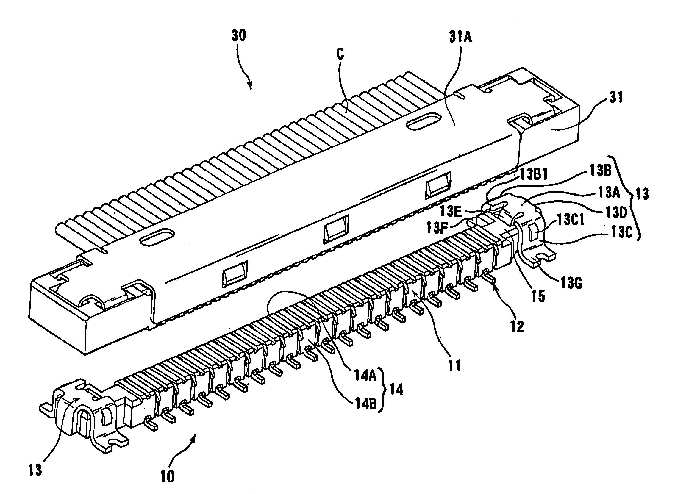
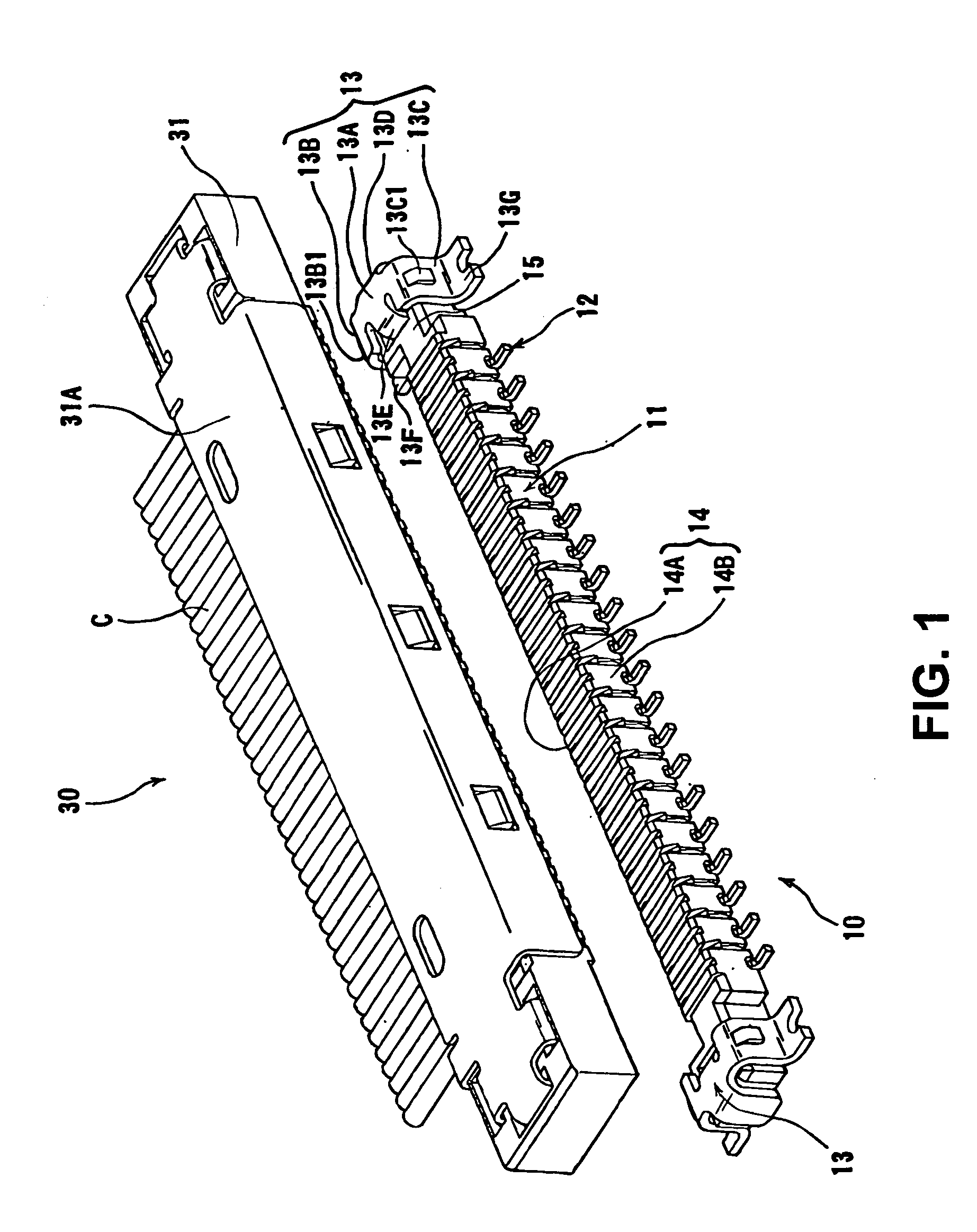
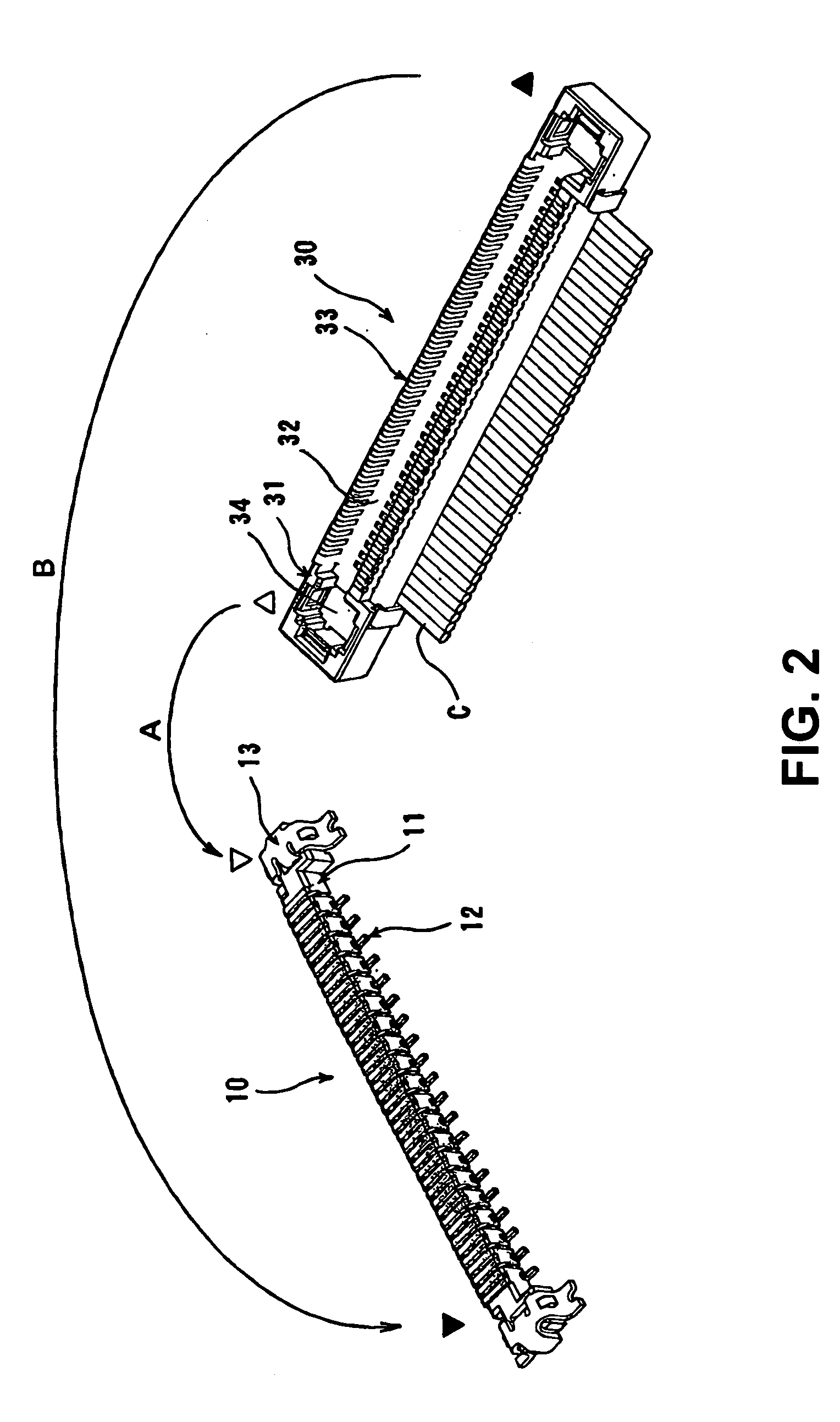
[0036]FIG. 1 is a perspective view showing a male connector 10 and a female connector 30 before the female connector 30 is fitted into the male connector 10 according to an embodiment of the present invention. FIG. 2 is a perspective view of the connector 10 and the female connector 30 having a fitting side that is inversed to be positioned on an upper side.

[0037]As shown in FIG. 2, the male connector 10 is fitted into the female connector 30 at fitting portions thereof. Accordingly, one of the fitting portions of the male connector 10 and the female connector 30 are indicated by Δ and ∇, while the other of the fitting portions of the male connector 10 and the female connector 30 are indicated by ▴ and ▾, respectively.

[0038]In the embodiment, the male connector 10 and the female connector 30 are fitted into each other from Δ to ∇ and ▴ to ▾ as indicated by arrows A and...


PUM


Abstract

An electrical connector includes a housing having a first sidewall surface and a second sidewall surface extending in a first direction in parallel to each other with a first distance therebetween; a first terminal having a first contact portion protruding from the first sidewall surface in a second direction substantially perpendicular to the first direction; a second terminal having a second contact portion protruding from the second sidewall surface; and an extension portion having a first external wall surface and a second external wall surface. The extension portion is arranged so that a center point between the first external wall surface and the second external wall surface is shifted with respect to a center point between the first contact portion and the second contact portion. The first external wall surface extends in parallel to the second external wall surface with a second distance larger than the first distance.

Description

BACKGROUND OF THE INVENTION AND RELATED ART STATEMENT[0001]The present invention relates to an electrical connector to be attached to a circuit board and a combination connector having the electrical connector.[0002]Patent Reference has disclosed a connector, in which contact portions of terminals are arranged on both sidewall surfaces of a housing that extends laterally on a circuit board. Such a connector is, in many cases, required to be small. Accordingly, in the connector, a dimension between the both sidewall surfaces is required to be small as well as dimensions thereof in a terminal arrangement direction; that is, a longitudinal direction thereof, and in a height direction thereof.Patent Reference: Japanese Patent Publication No. 3119722[0003]In the connector disclosed in Patent Reference, the contact portions of the terminals are arranged on the both sidewall surfaces of the housing. Further, the connector is attached to the circuit board as a male connector. In the male co...

Claims


Application Information

Patent Timeline
Patent Type & Authority Applications(United States)
IPC IPC(8): H01R12/00H01R12/57
CPCH01R12/57H01R12/592H01R13/639H01R12/79H01R12/716H01R12/51H01R12/55
Inventor ONO, SHOZO
Owner HIROSE ELECTRIC GROUP
Why Eureka
Try Eureka