Vehicle Wheel Optical Target Mounting Assembly

a technology for mounting assemblies and vehicles, applied in the direction of instruments, measuring devices, using fluid means, etc., can solve the problems of increased cost and construction costs, increased clamping force, and increased cost and complication of the adaptor system

Active Publication Date: 2008-09-04
HUNTER ENG
View PDF20 Cites 37 Cited by
  • Summary
  • Abstract
  • Description
  • Claims
  • Application Information

AI Technical Summary

Benefits of technology

[0026]FIG. 10 is a perspective view of the optical target mounting assembly of FIG. 1 secured to a vehicle wheel assembly.

Problems solved by technology

Traditional wheel adaptors that will universally adapt to the wide range of wheel sizes on the market today are difficult to design and costly to build.
Many times additional parts are required, such as extenders, in order to allow the adaptor to work with wheels that are very small or very large which also adds additional cost and complication to the adaptor system.
Additionally, traditional adaptors have to provide a substantial amount of clamping force in order to hold the weight of the target or sensor on the wheel assembly.
This clamping force can scratch or dent the wheel assembly where it is attached.
This is very undesirable especially when the wheel assembly is a very costly aftermarket wheel.

Method used


Image

  • Vehicle Wheel Optical Target Mounting Assembly
  • Vehicle Wheel Optical Target Mounting Assembly
  • Vehicle Wheel Optical Target Mounting Assembly

Examples


Embodiment Construction

[0028]The following detailed description illustrates the invention by way of example and not by way of limitation. The description clearly enables one skilled in the art to make and use the invention, describes several embodiments, adaptations, variations, alternatives, and uses of the invention, including what is presently believed to be the best mode of carrying out the invention.

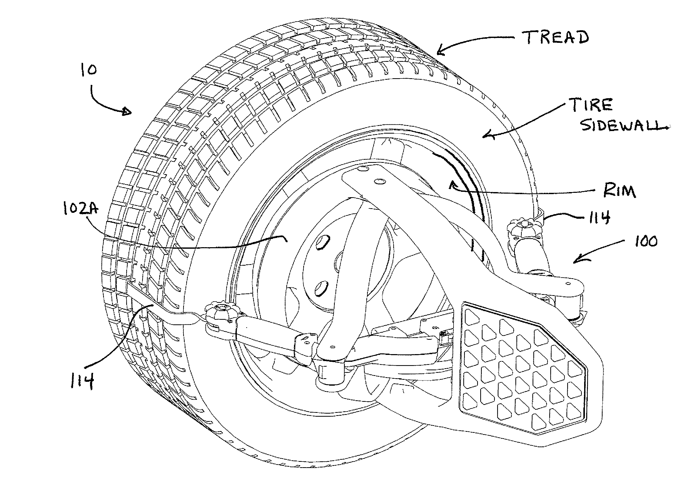
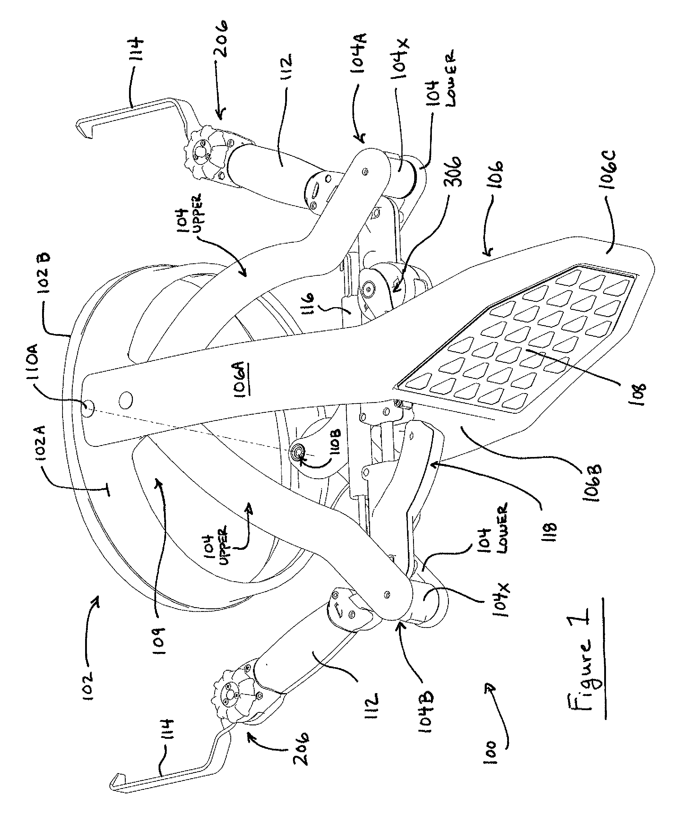
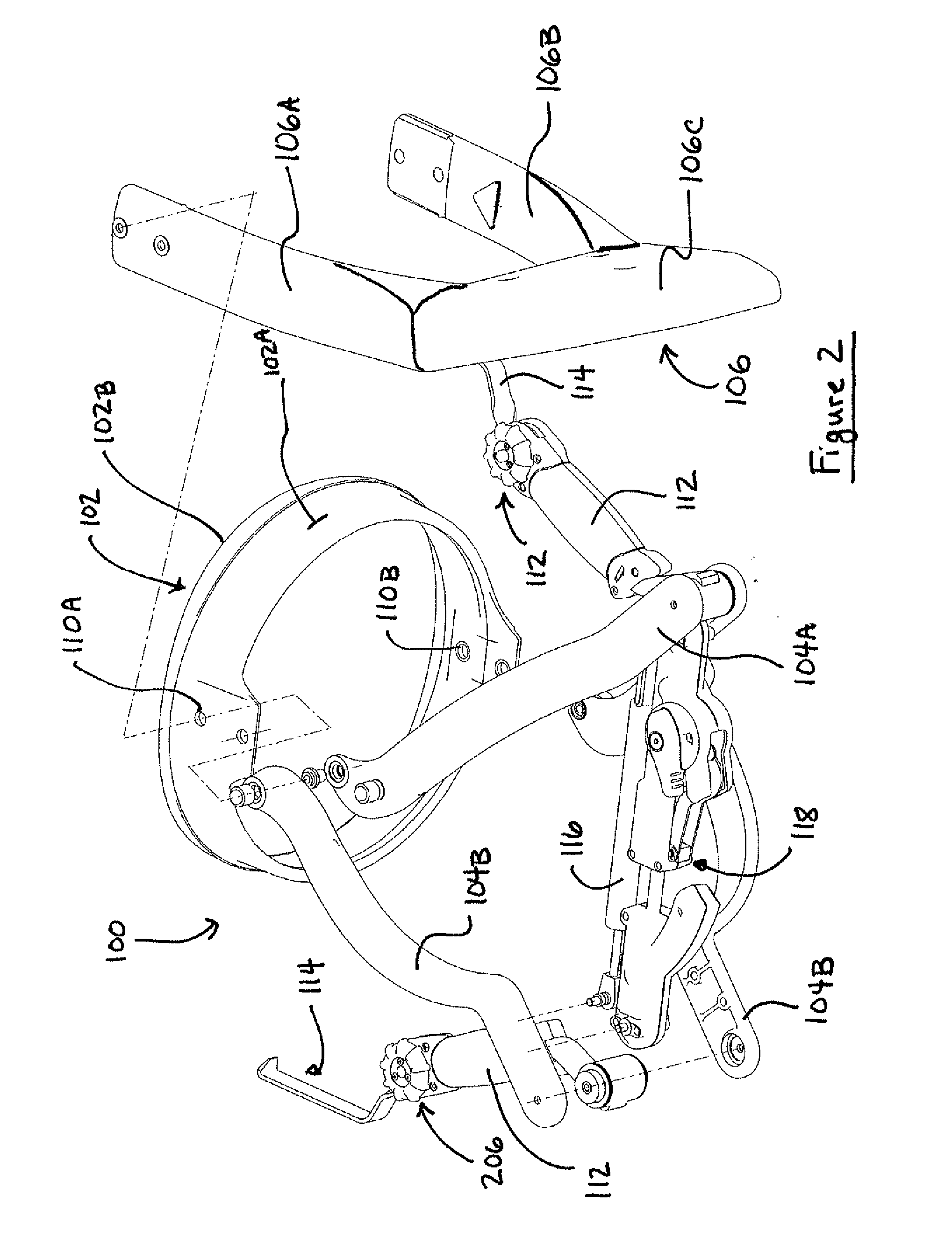
[0029]Turning to FIG. 1, an embodiment of the optical target assembly 100 of the present invention is shown in a perspective view. The optical target assembly 100 consists of a base assembly 102, a pair of pivot arm assemblies 104A and 104B pivotally coupled to the base assembly 102, a target support assembly 106 rigidly coupled to the base assembly 102, and an optical target 108 integrated into the target support assembly 106. Those of ordinary skill will recognize that the base 102 may be of unitary construction or of any other suitable configuration.

[0030]The optical target 108 provides visible feature...


PUM


Abstract

A machine vision vehicle wheel alignment system optical target assembly which incorporates an adaptor for attachment of an optical target to a vehicle wheel assembly. The adaptor includes a circular sinusoidal edge for seating in a non-determined position against surfaces of a vehicle wheel assembly, and a pair of pivoting arm assemblies capable of independent movement which are configured to position tire hooks for gripping the tread surfaces of a tire mounted to the wheel rim. Forces exerted between the pivoting arms are transferred to the tire hooks to hold the optical target assembly in contact with the wheel assembly surface. The optical target is integrated into the adaptor, and maintained in a stationary relationship to the wheel assembly thereby during a vehicle wheel alignment procedure.

Description

CROSS-REFERENCE TO RELATED APPLICATIONS[0001]The present application is related to, and claims priority from U.S. Provisional Patent Application Ser. No. 60 / 938,947 filed on May 18, 2007, which is herein incorporated by reference. The present application is further a continuation-in-part of co-pending U.S. patent application Ser. No. 11 / 535,881 filed on Sep. 27, 2006 which is related to, and claims priority from, U.S. Provisional Patent Application Ser. No. 60 / 721,206 filed on Sep. 28, 2005, both of which are herein incorporated by reference.STATEMENT REGARDING FEDERALLY SPONSORED RESEARCH[0002]Not Applicable.BACKGROUND OF THE INVENTION[0003]The present invention relates to machine vision vehicle service systems, and in particular to an optical target assembly configured for mounting to a surface of a vehicle, such as a vehicle wheel, during a machine-vision vehicle wheel alignment procedure.[0004]A machine-vision vehicle service system, such as a vehicle wheel alignment system like...

Claims


Application Information

Patent Timeline
Patent Type & Authority Applications(United States)
IPC IPC(8): G01B5/24
CPCG01B11/2755G01B2210/30G01B2210/14
Inventor STIEFF, MICHAEL T.MEYER, GREGORY F.LINSON, DENNIS M.
Owner HUNTER ENG
Why Eureka
Try Eureka