Chassis dynamometer

a dynamometer and chassis technology, applied in the direction of instruments, apparatus for force/torque/work measurement, instruments, etc., can solve the problem of not being able to accurately measure the amount of load transmitted from the drive wheel to the drum or roller, and achieve the effect of preventing the progress of the shi

Inactive Publication Date: 2008-09-04
KOKUSAI KEISOKUKI KK
View PDF11 Cites 18 Cited by
  • Summary
  • Abstract
  • Description
  • Claims
  • Application Information

AI Technical Summary

Problems solved by technology

Therefore, in the conventional chassis dynamometer, a torque meter is attached to the rotation shaft of the motor, and an amount of the mechanical loss is presumed from a detection result by the torque meter, calibrating an output of the load sensor with the presumed amount of the mechanical loss.
However, since the presumed mechanical loss contains an error, it has not been easy to make accurate measurement of the amount of the load transmitted from the drive wheel to the drum or rollers.

Method used


Image

  • Chassis dynamometer
  • Chassis dynamometer
  • Chassis dynamometer

Examples


Embodiment Construction

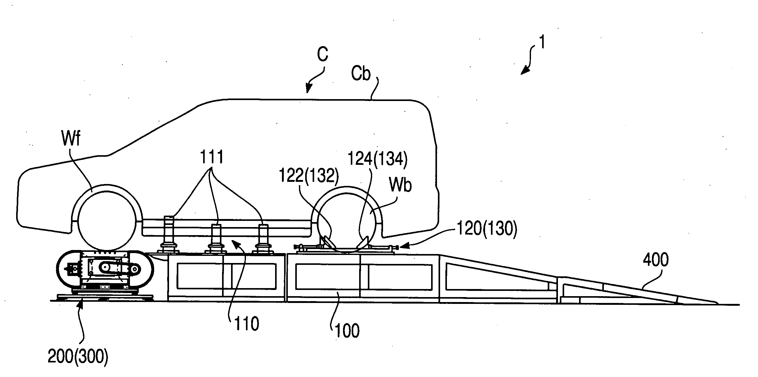
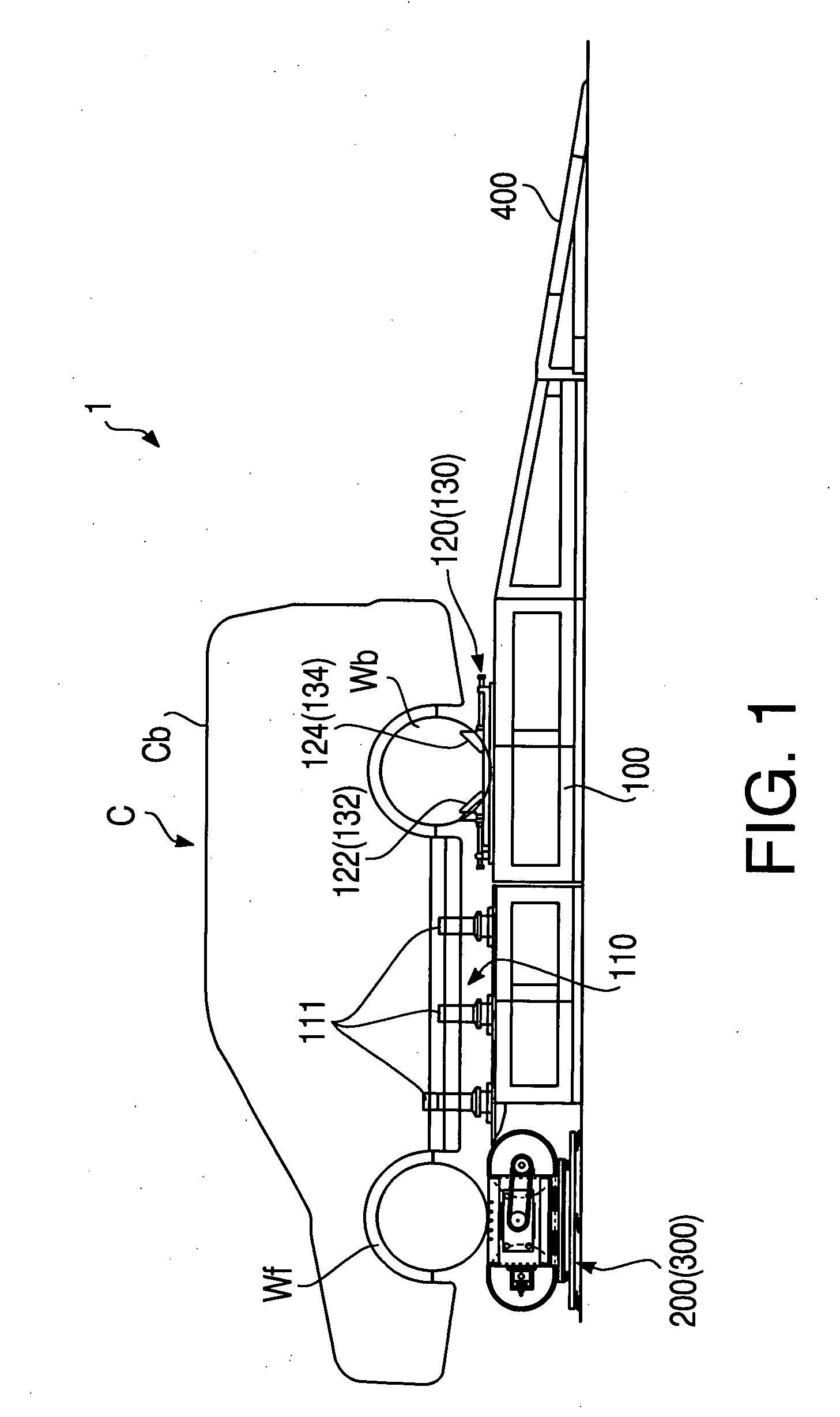
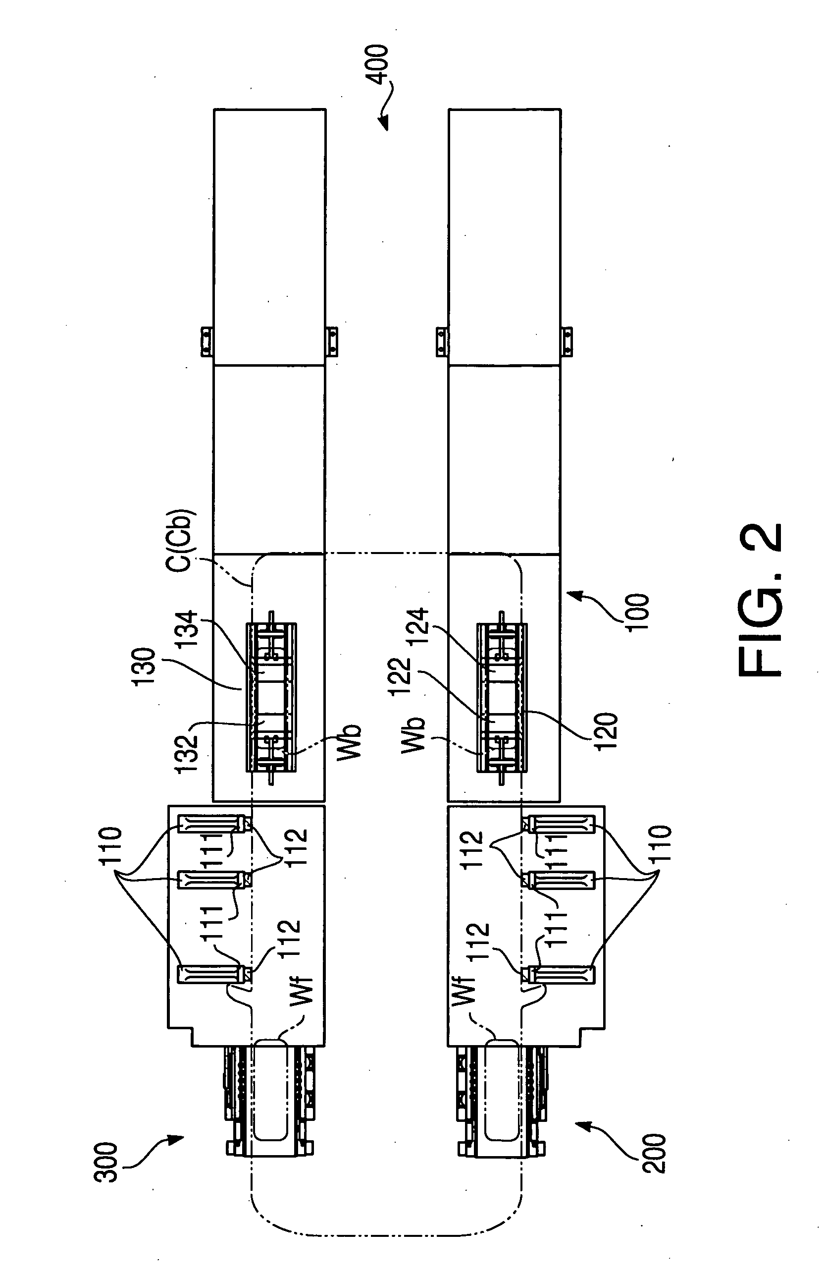
[0018]Hereinafter, an embodiment according to the present invention will be described with reference to the accompanying drawings. FIG. 1 is a side view of a chassis dynamometer 1 as a traveling test apparatus in the embodiment according to the present invention. In addition, FIG. 2 is a top view of the chassis dynamometer 1. The chassis dynamometer 1 is an apparatus configured to provide a drive wheel of a car (a front tire in the present embodiment) with traveling conditions similar to those while the car is actually traveling and perform various measurements. The measurement data are transmitted to a control unit 800 (described below) of the chassis dynamometer 1 and processed by the control unit 800.

[0019]As shown in FIG. 1, the chassis dynamometer 1 includes a base stage 100 for holding a lower portion of a body of a car C to be tested from both sides of the car C in a width direction, a pair of flat-belt mechanisms 200 and 300 (see FIG. 2) on which two front tires Wf of the ca...


PUM


Abstract

A chassis dynamometer includes a flat-belt mechanism configured such that a drive wheel of a vehicle is placed thereon, which includes a rotating member configured to be rotated by rotation of the drive wheel, a bearing portion configured to rotatably support the rotating member, a motor configured to apply a resistance to the rotation of the rotating member, and a bearing supporting member to which a housing of the bearing portion and the motor are fixed, a base configured to support the bearing supporting member from beneath the bearing supporting member, a plurality of three-component force sensors arranged between the bearing supporting member and the base to measure a force transmitted from the drive wheel to the flat-belt mechanism, and a computing unit configured to compute moments with respect to three axes based on measurement results of the plurality of three-component force sensors.

Description

CROSS-REFERENCE TO RELATED APPLICATION[0001]This is a Continuation Application based on International Application No. PCT / JP2006 / 318950 filed on Sep. 25, 2006, which claims priorities from Japanese Patent Applications No. 2005-278911 and No. 2005-278912, both filed on Sep. 26, 2005. The entire disclosures of the prior applications are incorporated herein by reference.BACKGROUND[0002]1. Field of the Invention[0003]The present invention relates to a vehicle traveling test apparatus, such as a chassis dynamometer, configured to cause a wheel of a vehicle such as a car to rotate in a state where a frame of the vehicle is kept still and to carry out various tests for the car.[0004]2. Related Art[0005]Recently, instead of letting a car travel on a test course, a traveling test apparatus by which various measurements are carried out by driving the car in a room is being utilized. In the traveling test apparatus, a drive wheel of the car is caused to contact a drum or an endless belt, and a...

Claims


Application Information

Patent Timeline
Patent Type & Authority Applications(United States)
IPC IPC(8): G01M17/007G01M17/04
CPCG01M17/0074G01L5/167B65H5/02G01N2203/0676
Inventor MATSUMOTO, SIGERU
Owner KOKUSAI KEISOKUKI KK
Why Eureka
Try Eureka