Composite Superconductor Cable Produced by Transposing Planar Subconductors

a superconductor cable and superconductor technology, applied in the direction of superconducting magnets/coils, superconductor devices, magnetic bodies, etc., can solve the problems of reducing the overall engineering current density of windings and predicting even more difficulty in edgewise deformation

Inactive Publication Date: 2008-09-04
CALLAGHAN INNOVATION RES LTD
View PDF9 Cites 27 Cited by
  • Summary
  • Abstract
  • Description
  • Claims
  • Application Information

AI Technical Summary

Benefits of technology

The technical effect of this patent is that it describes how to make an electrical connector made from high-temperature superconductors. These connectors are designed by arranging individual parts called conductor elements, which can be easily assembled into cables with good performance at very low temperatures.

Problems solved by technology

The technical problem addressed in this patent text needs to be identified by a senior R&D personnel who has read it through.

Method used


Image

  • Composite Superconductor Cable Produced by Transposing Planar Subconductors
  • Composite Superconductor Cable Produced by Transposing Planar Subconductors
  • Composite Superconductor Cable Produced by Transposing Planar Subconductors

Examples


Embodiment Construction

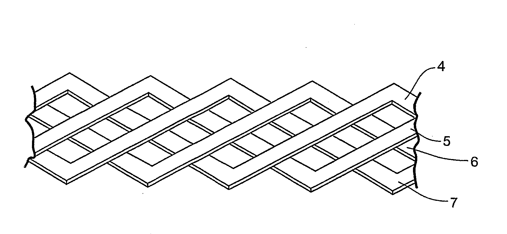
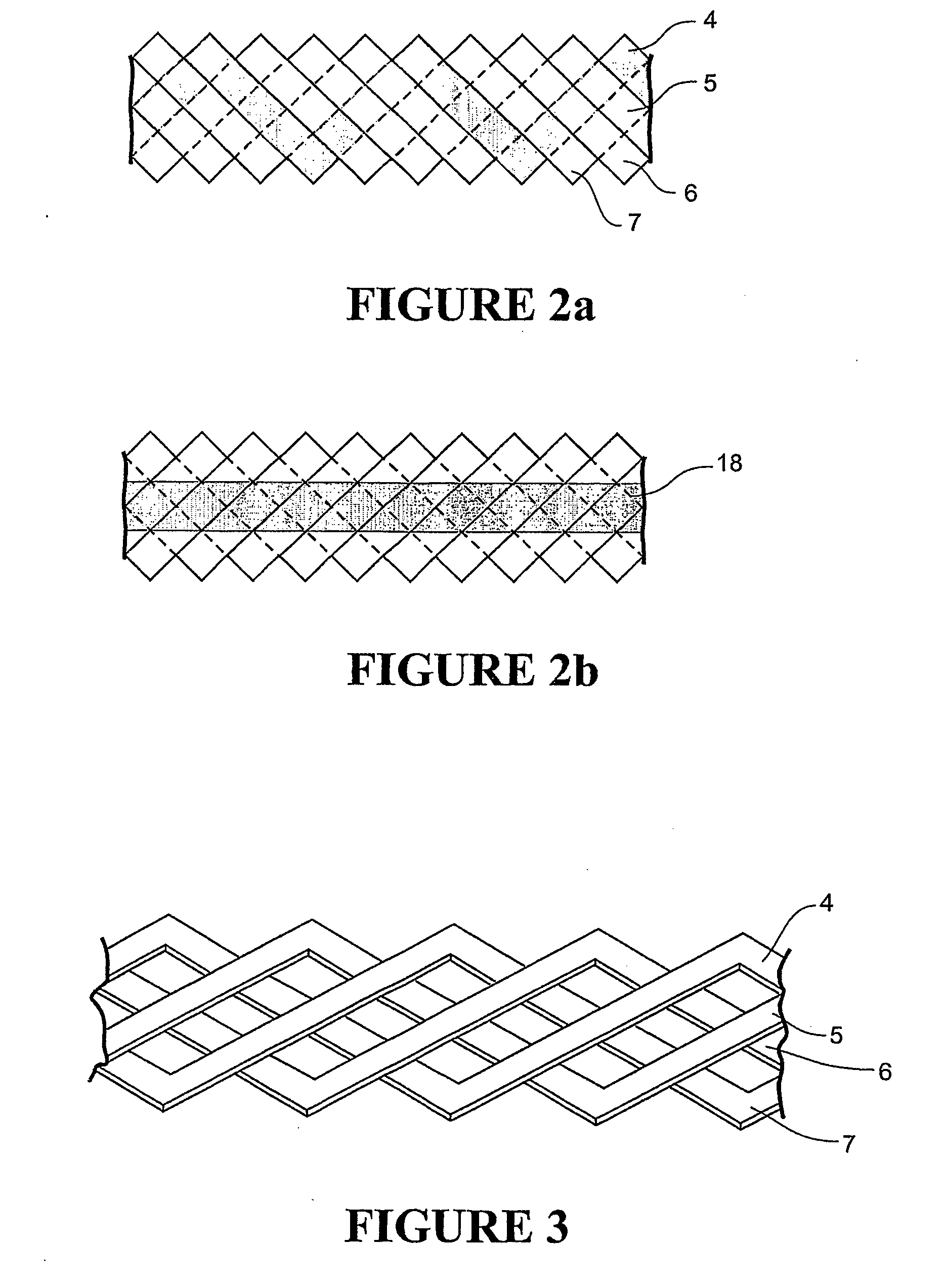
[0031]The present invention comprises to the forming of high current and / or low AC loss transposed conductor or cable from 2G wire or similar coated conductor without the need for substantial in-plane deformation by, in one form, cutting the serpentine subconductors from one or more wider common planar substrate or tape. The required number of subconductors may then be assembled or interleaved, typically using a planetary winder with appropriate lengthwise displacement of each subconductor in cyclic order, to form a transposed conductor or cable. This may then be further treated to fix the individual subconductors in place for subsequent handling, manufacturing, and implementation operations, preferably using methods which optimise the interstrand resistivity to achieve low AC loss.

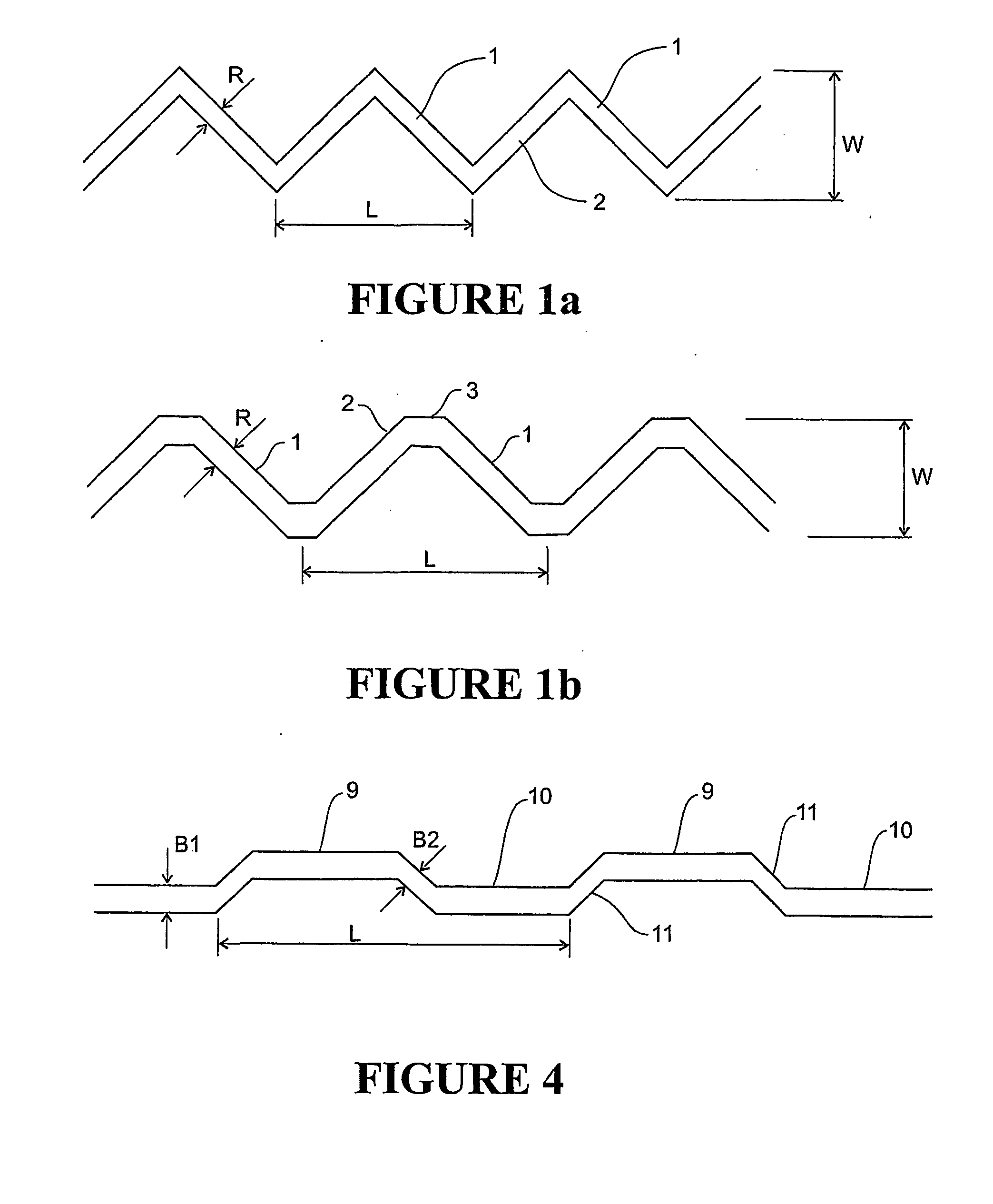
[0032]The subconductors may be cut or precut from the substrate(s), such that wastage may be minimized, before or after formation of the superconducting layer and all or some of any buffer layers on the s...


PUM

PropertyMeasurementUnit
Lengthaaaaaaaaaa
Angleaaaaaaaaaa
Widthaaaaaaaaaa

Abstract

A method of forming a low AC loss, fully transposed cabled superconductor from multiple superconducting subconductors cut in a serpentine form from a wider superconducting tape is disclosed. By assembling pre-cut subconductor tapes a cable with a short transposition pitch length can be formed without excessive in-plane or out-of-plane deformation of the tape which could otherwise cause degradation of its superconducting performance. The transposition may be in either Roebel bar or Rutherford cable geometry.

Description


Claims


Application Information

Patent Timeline
Owner CALLAGHAN INNOVATION RES LTD
Why Eureka
Try Eureka