
Image-capturing apparatus and image processing method

Active Publication Date: 2008-09-04
SONY CORP
View PDF5 Cites 15 Cited by
  • Summary
  • Abstract
  • Description
  • Claims
  • Application Information

AI Technical Summary

Benefits of technology

[0011]According to the embodiments of the present invention, a predetermined process is performed on image data in a RAW format, which is sequentially output from the image-capturing means as a result of a continuous series of image capturing operations. The generated processed image data related to each captured image is selectively output to a plurality of image processing circuits. Image processing including a luminance / color-difference conversion process and a data compression process related to each captured image is shared among a plurality of image processing circuits. As a result, it is possible to perform fast image processing on a series of captured images obtained by the continuous image capturing.

Problems solved by technology

However, in the technology of Japanese Unexamined Patent Application Publication No. 2002-94934, since only one image processing circuit is connected to the image processing system bus, it is difficult to start processing for the next image until the processing currently being performed in the image processing circuit is completed.
As a result, it is difficult to set a continuous image-capturing speed shorter than the processing time in the image processing circuit in the continuous image capturing, and it is difficult to perform fast image processing on a series of captured images obtained by continuous image capturing.
Therefore, it is difficult to realize the above-described high-speed continuous image-capturing performance.

Method used


Image

  • Image-capturing apparatus and image processing method
  • Image-capturing apparatus and image processing method
  • Image-capturing apparatus and image processing method

Examples


first embodiment

[0022]

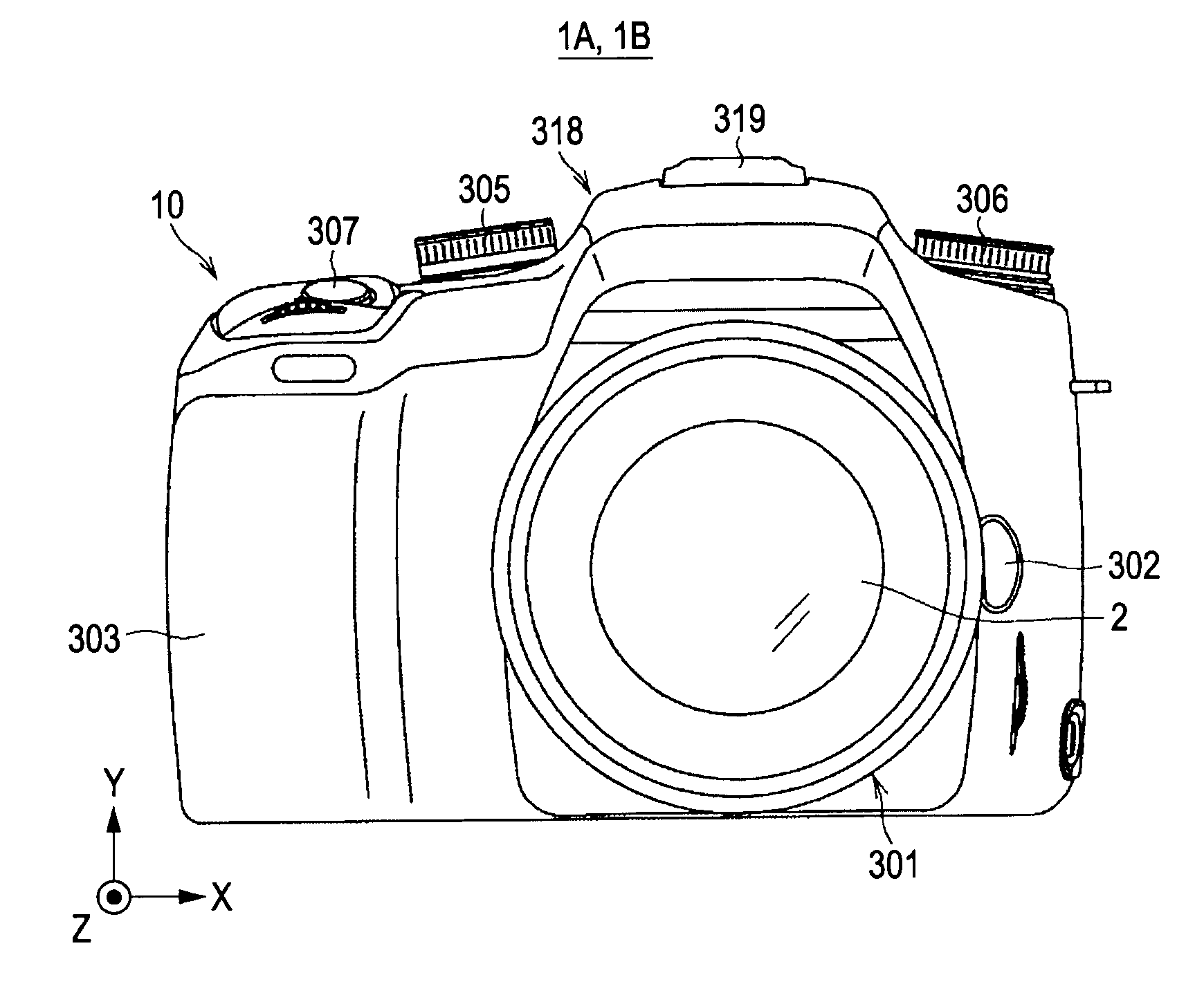
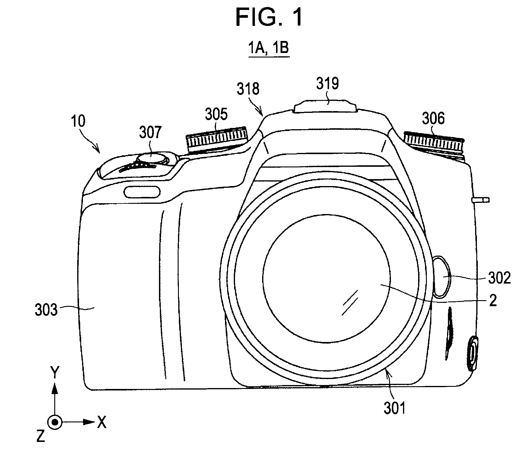
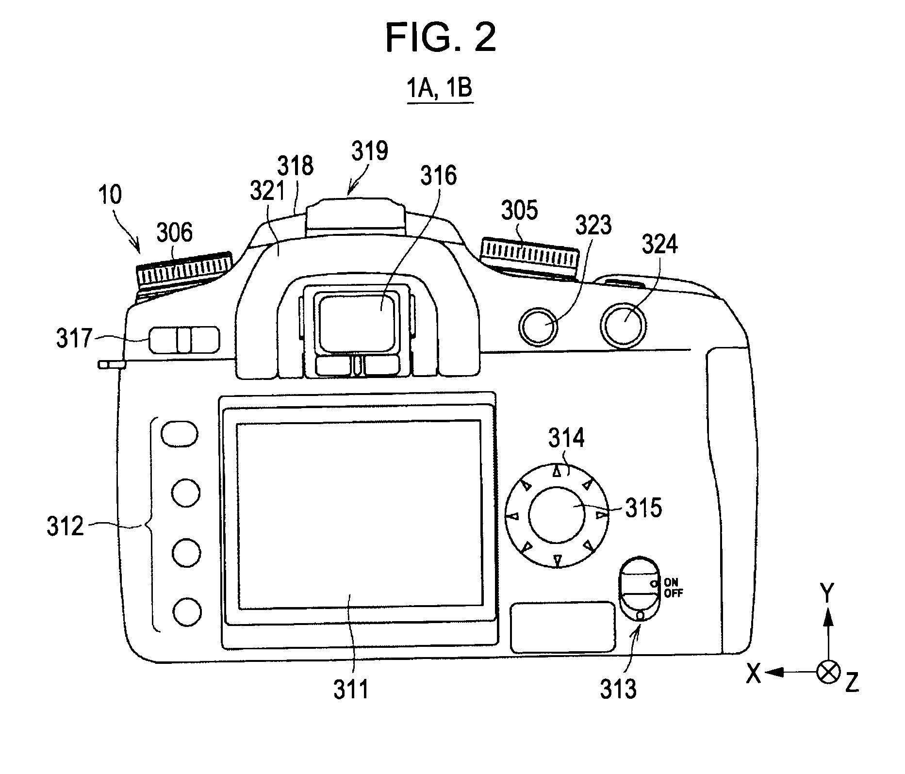
[0023]FIGS. 1 and 2 show the configuration of the exterior of a camera system 1A according to a first embodiment of the present invention. FIGS. 1 and 2 show a front view and a back view, respectively.

[0024]The camera system 1A functions as an image-capturing apparatus configured as, for example, a single-lens-reflex digital still camera, and includes a camera body 10, and an exchangeable lens 2 that can be loaded into and removed from the camera body 10.

[0025]In FIG. 1, on the front side of the camera body 10, there are provided a mount unit 301 in which an exchangeable lens 2 is installed in nearly the center of the front side, a lens exchange button 302 arranged on the right side of the mount unit 301, a grip part 303, which is protrusively provided in the left end portion of the front side (the left side in the X direction) and which can be reliably gripped by a user with one hand (or both hands), a mode setting dial 305 arranged in the left upper portion of the front side...

second embodiment

[0125]

[0126]A camera system 1B according to a second embodiment of the present invention has an exterior configuration identical to that of the camera system 1A according to the first embodiment of the present invention shown in FIGS. 1 and 2.

[0127]FIG. 9 is a block diagram showing the electrical configuration of the camera system 1B. FIG. 9 corresponds to the block diagram of the first embodiment shown in FIG. 3, and components in FIG. 9, which are the same as those components shown in FIG. 3, are designated with the same reference numerals.

[0128]The camera system 1B has an electrical configuration similar to the camera system 1A of the first embodiment. However, the configuration for a process for recording compressed image data output from the back engine 5 differs.

[0129]More specifically, the main difference is that, in the camera system 1B, a recording controller 42 corresponding to the recording controller 411 (see FIGS. 4 and 5) of the front engine 4 according to the first em...


PUM


Abstract

An image-capturing apparatus includes an image-capturing unit configured to sequentially output image data in a RAW format related to each of captured images as a result of a continuous series of image capturing operations; a signal processor configured to perform a predetermined process on the image data in a RAW format and output processed image data; image processing circuits configured to perform a luminance / color-difference conversion process and a data compression process on the processed image data and output compressed image data; and a recording controller configured to cause compressed image data output from the image processing circuits to be recorded in a predetermined recorder. The signal processor includes a selection output unit configured to selectively output the processed image data related to each of the captured images to the image processing circuits and cause the image processing related to each captured image to be shared by the image processing circuits.

Description

CROSS REFERENCES TO RELATED APPLICATIONS[0001]The present invention contains subject matter related to Japanese Patent Application JP 2007-052280 filed in the Japanese Patent Office on Mar. 2, 2007, the entire contents of which are incorporated herein by reference.BACKGROUND OF THE INVENTION[0002]1. Field of the Invention[0003]The present invention relates to a technology for an image-capturing apparatus capable of performing a continuous series of image capturing operations (continuous image capturing).[0004]2. Description of the Related Art[0005]In digital cameras (image-capturing apparatuses), with increases in the number of pixels included in an image-capturing sensor (imaging sensor), there has been a tendency that the processing performance of an image processing circuit that performs JPEG compression is insufficient. Here, if the processing performance of an image processing circuit becomes insufficient, it is difficult for a single-lens reflex digital camera demanding high-s...

Claims


Application Information

Patent Timeline
IPC IPC(8): H04N5/76H04N9/77H04N5/232H04N5/243H04N5/335H04N5/91H04N101/00
CPCH04N5/765H04N5/772H04N5/907H04N9/8047H04N9/8205H04N9/8227H04N2101/00H04N23/667H04N23/80
Inventor FUJISAWA, TOSHIKISHIONO, TORUYANO, HITOSHIMAEHAMA, SHINICHIFUKUDA, AKIRANARA, SHINYA
Owner SONY CORP
Learn More