Hearing apparatus having a receiver compensation coil

a receiver and compensation coil technology, applied in the direction of electrical devices, stereophonic communication headphones, electric transducers, etc., can solve the problems of inability to reach the antenna coil outwardly, the magnetic field generated by the receiver coil cannot be fully used, and the magnetic field of the receiver coil cannot be used fully and partially lost, etc., to achieve sufficient mechanical robustness and reduce the space of the electrical coil

Inactive Publication Date: 2008-09-04
SIEMENS AUDIOLOGISCHE TECHN
View PDF12 Cites 16 Cited by
  • Summary
  • Abstract
  • Description
  • Claims
  • Application Information

AI Technical Summary

Benefits of technology

[0010]It is thus advantageously possible to produce a favorable receiver with effective magnetic shielding. In this way, the electrical coil can be directed to the receiver housing such that precisely the magnetically sensitive components in the hearing apparatus, e.g. the telephone coil, are shadowed.
[0013]Furthermore, the electrical coil expediently has a polyimide substrate as a carrier. This can be used in particular as a foil. The foil carrier also allows the required space of the electrical coil to be reduced further. The polyimide also provides for an adequate electrical insulation and is also sufficiently mechanically robust.

Problems solved by technology

The magnetic field generated in this process cannot be used fully and is partially lost as an interference field into the ambient.
Otherwise the magnetic field of the receiver interferes with the telephone coil installed in the hearing device for instance.
This means that the magnetic field generated by the receiver coil is not able to outwardly reach the antenna coil.
A complete decoupling of both coils can however only be achieved with difficulty.
However, a very complex component is thus produced and exchanging the receiver is always associated with exchanging the antenna coil for instance.

Method used


Image

  • Hearing apparatus having a receiver compensation coil
  • Hearing apparatus having a receiver compensation coil

Examples


Embodiment Construction

[0017]The exemplary embodiment illustrated in more detail below represents a preferred embodiment of the present invention.

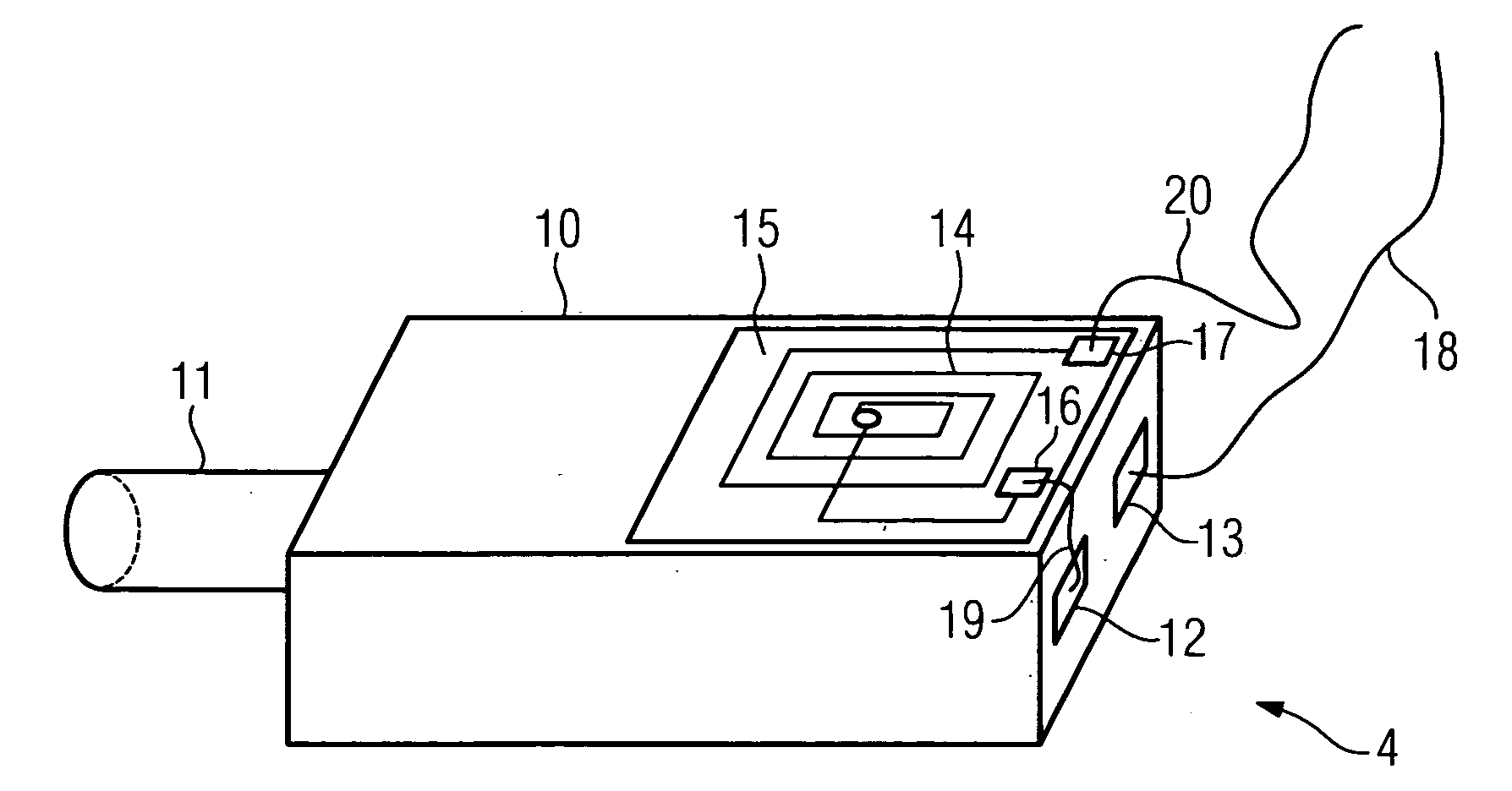
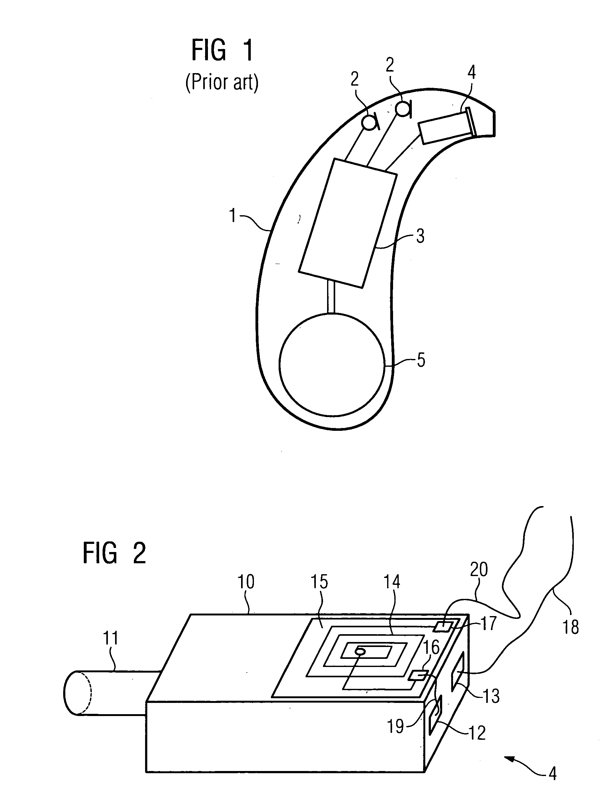
[0018]The receiver 4 shown in the example of FIG. 2 has a receiver housing 10 and a connecting piece attached thereto as a sound outlet. The housing 10 is shown here in the manner of a cuboid but can also be configured for instance in the manner of a cylinder or in any other arbitrary form. The edges and corners may also be rounded.

[0019]Contacts 12, 13 for wiring the receiver 4 are arranged on the side of the receiver housing 10 facing the connecting piece 11. These contacts 12, 13 can naturally also be arranged on another point of the receiver housing 10.

[0020]In the example in FIG. 2, a helical air-core coil 14 is attached to the topside of the receiver housing 10. It is attached to a polyimide foil 15. Coil contacts 16, 17, which are connected to both ends of the coil 14, are also located on the polyimide foil 15.

[0021]Overall, the polyimide foil with the el...


PUM


Abstract

A receiver of a hearing apparatus and in particular a hearing device is to be shadowed in a simple fashion against other magnetically sensitive components. To this end, an electrical coil is provided, which is attached directly to a segment of the receiver housing. The principle axis of the electrical coil is at right angles to the surface of the segment of the receiver housing. The electrical coil is also connected in series to the receiver. For compensation purposes, the electrical coil forms a corresponding counter field for the interference field of the receiver. A compensation coil of this type is easy to assemble and space-saving.

Description

CROSS REFERENCE TO RELATED APPLICATIONS[0001]This application claims priority of German application No. 10 2007 007 800.7 filed Feb. 16, 2007, which is incorporated by reference herein in its entirety.FIELD OF THE INVENTION[0002]The present invention relates to a hearing apparatus with a receiver, which has a receiver housing, and an electrical coil, which is attached directly to one segment of the receiver housing. The term hearing apparatus is understood here to mean in particular a hearing device, a headset, earphones or suchlike.BACKGROUND OF THE INVENTION[0003]Hearing devices are portable hearing apparatuses which are used to supply the hard-of-hearing. To accommodate the numerous individual requirements, different configurations of hearing devices such as behind-the-ear hearing devices (BTE), in-the-ear hearing devices (ITE), e.g. including conch hearing devices or channel hearing devices (CIC), are provided. The hearing devices designed by way of example are worn on the outer...

Claims


Application Information

Patent Timeline
Patent Type & Authority Applications(United States)
IPC IPC(8): H04R25/00
CPCH04R1/1091H04R5/033H04R2420/07H04R2225/49H04R2225/51H04R25/554
Inventor CHAN, HOONG YIHKASZTELAN, THOMASKOO, WEE HAW
Owner SIEMENS AUDIOLOGISCHE TECHN
Why Eureka
Try Eureka