Roller blind with perforated band drive

a technology of perforated bands and roller blinds, applied in curtain accessories, curtain suspension devices, building components, etc., can solve the problem of substantial installation expenditures and achieve the effect of compact design

Inactive Publication Date: 2008-09-11
BOS
View PDF12 Cites 25 Cited by
  • Summary
  • Abstract
  • Description
  • Claims
  • Application Information

AI Technical Summary

Benefits of technology

[0005]In view of the foregoing, a general object of the present invention is to prov...

Problems solved by technology

The storage tube is installed in the car body beneath the rear window, in the...

Method used


Image

  • Roller blind with perforated band drive
  • Roller blind with perforated band drive
  • Roller blind with perforated band drive

Examples


Embodiment Construction

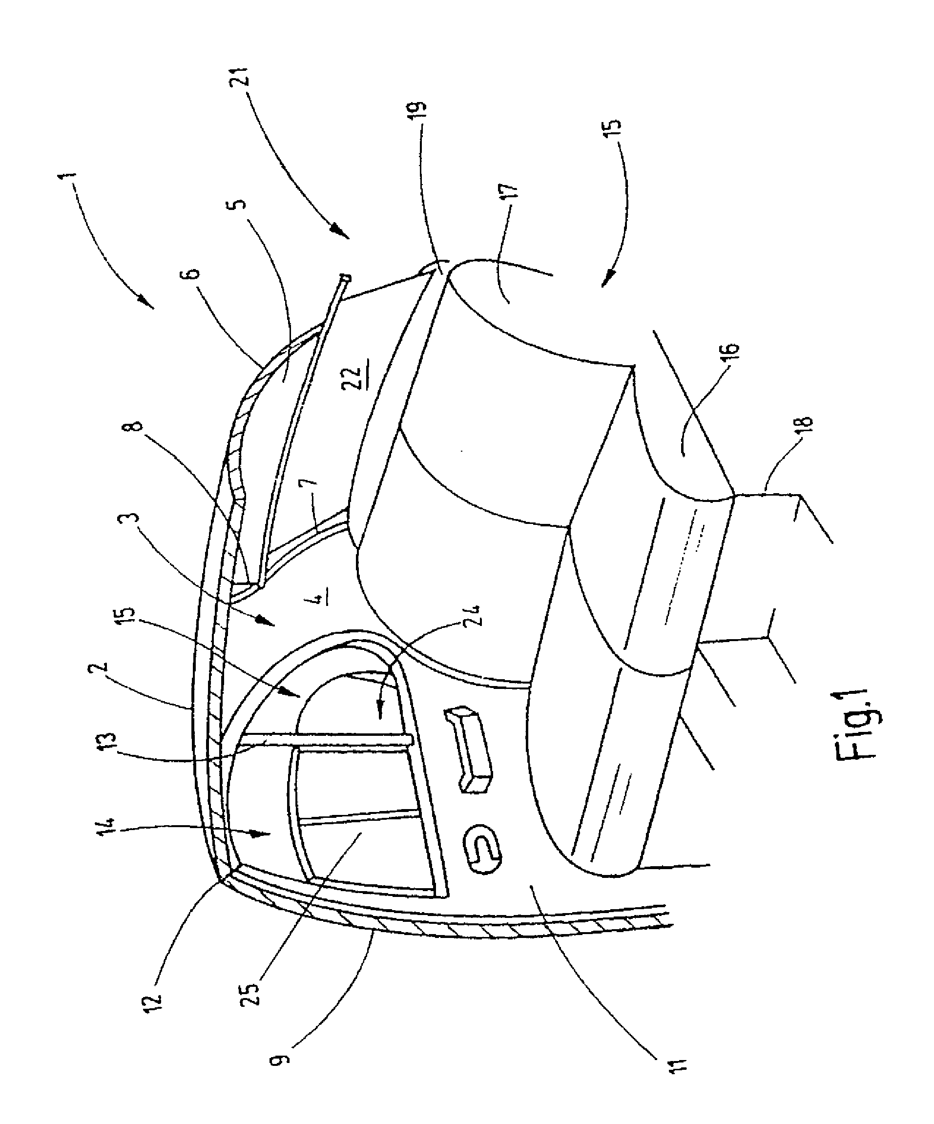
[0030]Referring now to FIG. 1 of the drawings, a rear seat region of an exemplary passenger car is shown. The right inner side of the rear seat region is shown, which is configured as a mirror image of the not-shown left inner side. If not indicated otherwise, the description of the right side of the car body also applies to the left side of the car body. FIG. 1 is simplified in that, for example, car body structures such as reinforcements and mounting elements are not illustrated because they are not essential for understanding the invention.

[0031]The car body section 1 shown features a roof 2. A C-column 3 extends laterally downward from the roof to a floor assembly. A corresponding C-column is also arranged on the other side of the motor vehicle. The C-column 3 is provided on its inner side with a trim panel 4. The roof 2 transitions on its rear edge into a rear window 5. The upper side of the rear window is defined by an upper window edge 6. However, only a section 7 of the late...


PUM


Abstract

A drive arrangement for roller blinds of motor vehicles is provided. The drive arrangement includes a housing that contains a chamber for accommodating a spring steel band that is pre-formed in a spiral shape in a similar manner to a clockwork spring. The spring steel band is equidistantly perforated in the longitudinal direction and moves over a drive gear that is configured similarly to a barbed wire and driven by a geared motor. The projections of the drive gear engage with the holes of the spring steel band.

Description

FIELD OF THE INVENTION[0001]This invention relates to roller blinds for motor vehicles and more particularly to a drive arrangement for such roller blinds.BACKGROUND OF THE INVENTION[0002]Remote-controlled window shades in motor vehicles require a motorized drive. Due to the fact that the roller blind consists of a non-rigid material, the roller blind cannot be pushed so that the far edge of the roller blind relative to the winding shaft must be moved away from the winding shaft in suitable fashion.[0003]This is the reason that the winding shaft for the window shade is pre-stressed in the wind-up direction of the roller blind by means of a spring drive using arrangements that are known from the state of the art. In order to unwind the roller blind in front of a window, the roller blind is provided with a pull rod having ends that are guided in guide rails. The guide rails simultaneously serve for guiding in a buckle-free manner toothed racks that have teeth all around their surface....

Claims


Application Information

Patent Timeline
IPC IPC(8): A47G5/02
CPCB60J1/2086B60J1/2027B60J3/02B60J3/00
Inventor WALTER, HERBERT
Owner BOS
Why Eureka
Try Eureka