Magnetic Repulsion Coupling for Transmission of a Rotational Movement from a Driving Member to a Driven Member

a technology of magnetic repulsion and transmission coupling, which is applied in the direction of dynamo-electric machines, electrical apparatus, portable percussive tools, etc., can solve the problems of reducing the torque value, affecting the transmission speed so as to prevent irreversible angular dephasing of the driving member, reduce the vibration, and increase the drive torque value

Inactive Publication Date: 2008-09-11
BARUFFALDI
View PDF7 Cites 13 Cited by
  • Summary
  • Abstract
  • Description
  • Claims
  • Application Information

AI Technical Summary

Benefits of technology

[0009]The technical problem which is posed, therefore, is to provide a coupling for transmission of a rotational movement from a driving member to a driven member, able to produce a substantial reduction in the vibrations transmitted from the former to the latter, so as to achieve higher drive torque values for the same dimensions and prevent irreversible angular dephasing of the driving member with respect to the driven member with a reduction in the drive torque.
[0010]In connection with this problem it is also required that this device should have small dimensions, be easy and inexpensive to produce and assemble and be able to be easily installed at any user facility using normal standardised connection means.

Problems solved by technology

It is known in the technical sector relating to the transmission of rotational movements from a driving member to a driven member that there is the need to dampen, during transmission, the vibrations which are produced by the driving member and could damage the driven member and / or the device to which it is connected.
This solution, however, has drawbacks arising from the fact that only very low torque values are possible with the coupling and, in the event of relative slipping of the driving member and driven member, there is a drastic reduction in the said torque value since the N-S permanent magnets are angularly out-of-phase and, no longer being situated opposite each other, reduce considerably the relative magnetic attraction.
In addition to this, once slipping has occurred, the speed of relative rotation is such that it is no longer possible to re-establish the angular phasing unless the device is stopped and reset to its initial condition.
The technical problem which is posed, therefore, is to provide a coupling for transmission of a rotational movement from a driving member to a driven member, able to produce a substantial reduction in the vibrations transmitted from the former to the latter, so as to achieve higher drive torque values for the same dimensions and prevent irreversible angular dephasing of the driving member with respect to the driven member with a reduction in the drive torque.

Method used


Image

  • Magnetic Repulsion Coupling for Transmission of a Rotational Movement from a Driving Member to a Driven Member
  • Magnetic Repulsion Coupling for Transmission of a Rotational Movement from a Driving Member to a Driven Member
  • Magnetic Repulsion Coupling for Transmission of a Rotational Movement from a Driving Member to a Driven Member

Examples


Embodiment Construction

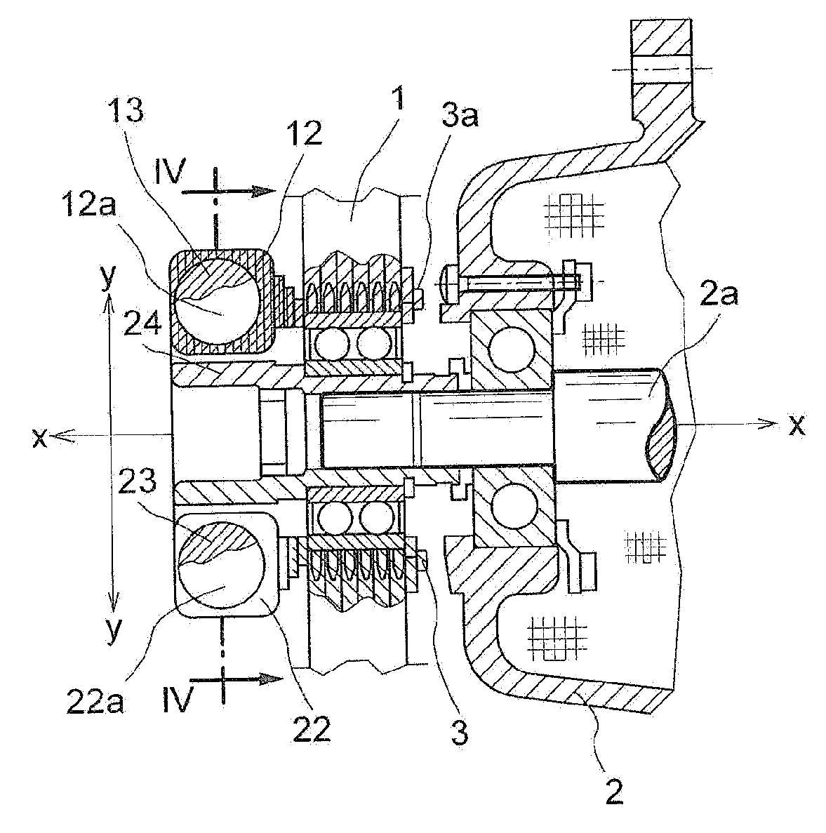
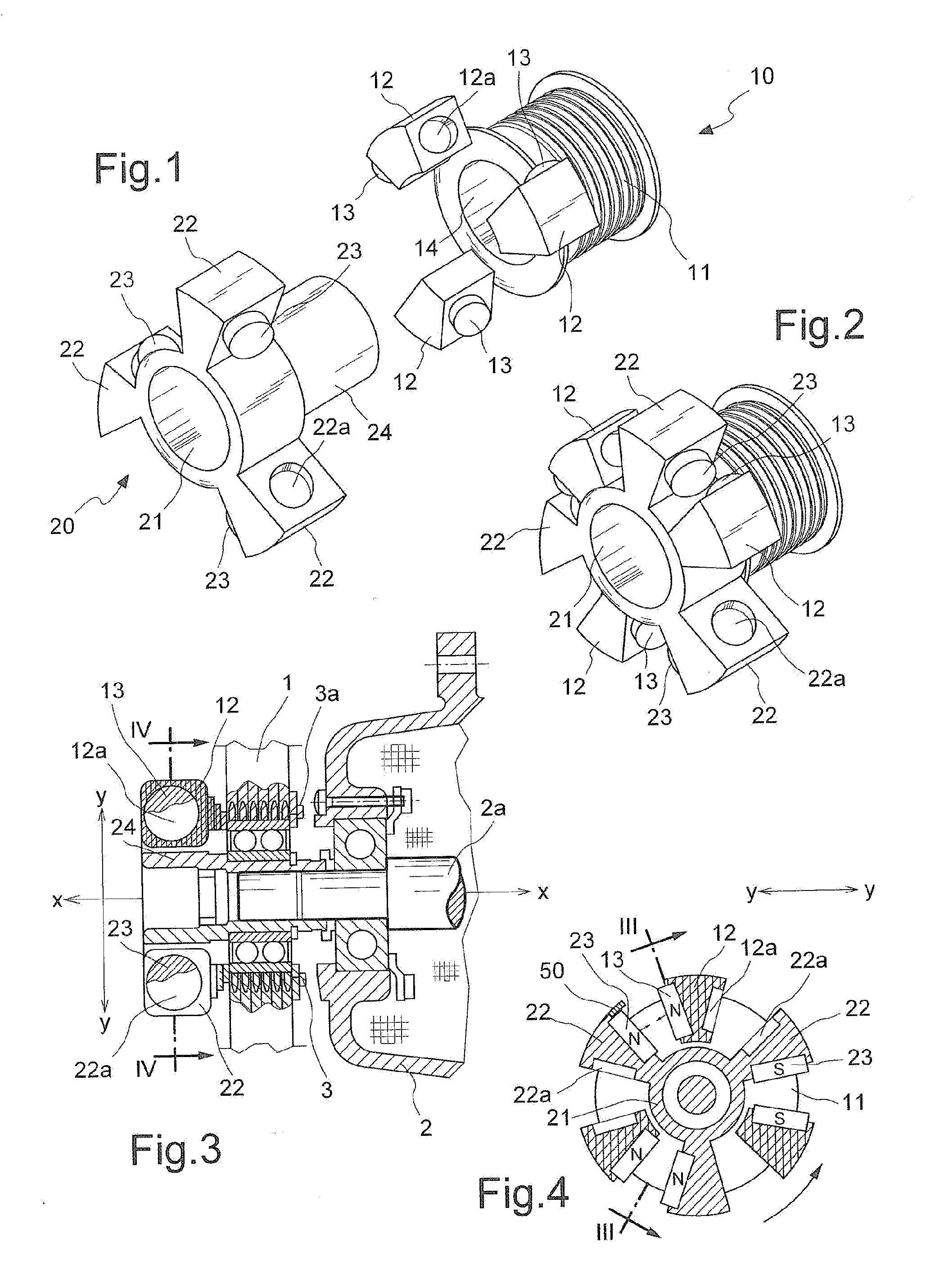
[0020]As shown in FIGS. 1-4 and assuming for the sole sake of convenience of the description and without a limiting meaning two reference axes, in a longitudinal direction X-X, coinciding with the axis of rotation, and in a transverse or radial direction Y-Y, respectively, the transmission coupling according to the present invention can include a driving member 10 with a longitudinal extension 11 formed in the manner of a pulley and suitable for engagement with a drive belt 1 connected, for example, to the shaft of an internal-combustion engine of a vehicle.

[0021]On the opposite side to the pulley 11, the driving member 10 has a plurality of axial projections 12—three in number in the example, arranged at 120°—each of which has formed internally a seat 12a able to contain a permanent magnet 13 which is arranged in a radial plane parallel to the axis of rotation.

[0022]The driving member 10 has internally a cylindrical through-seat or opening 14 able to allow the insertion of a sleeve...


PUM


Abstract

Coupling for transmission of a rotational movement from a driving member to a driven member, comprising permanent magnets which are integral with the driving member and permanent magnets which are integral with the driven member, said permanent magnets having a matching polarity (N-N;S-S) and lying in respective radial planes parallel to the axis of rotation and situated opposite each other so that each pair of oppositely facing magnets produces a corresponding magnetic repulsion force. The magnet transmission force transmits the rotational movement from the driving member to the driven member.

Description

BACKGROUND[0001]1. Technical Field of the Invention[0002]The present invention relates to a magnetic repulsion coupling for transmission of a rotational movement from a driving member to a driven member without relative contact.[0003]2. Description of the Prior Art[0004]It is known in the technical sector relating to the transmission of rotational movements from a driving member to a driven member that there is the need to dampen, during transmission, the vibrations which are produced by the driving member and could damage the driven member and / or the device to which it is connected.[0005]It is also known that, in order to find a solution to the problem, magnetically driven transmission couplings have been devised, these being able to avoid direct contact between the driving member and driven member and consequently absorb the vibrations transmitted by the former to the latter.[0006]These known couplings are based on the provision of permanent magnets with opposite polarities N-S, a...

Claims


Application Information

Patent Timeline
Patent Type & Authority Applications(United States)
IPC IPC(8): B25C7/00
CPCH02K49/104
Inventor BOFFELLI, PIERCARLOBELLOTTI, CLAUDIODEPOLI, ERMINIONATALE, FABIO
Owner BARUFFALDI
Why Eureka
Try Eureka