
Electrophoretic display with thermal control

a display and thermal control technology, applied in the field of display devices, can solve the problems of cross bias, visible optical density change, affecting the cross bias,

Active Publication Date: 2008-09-11
E INK CORPORATION
View PDF29 Cites 42 Cited by
  • Summary
  • Abstract
  • Description
  • Claims
  • Application Information

AI Technical Summary

Benefits of technology

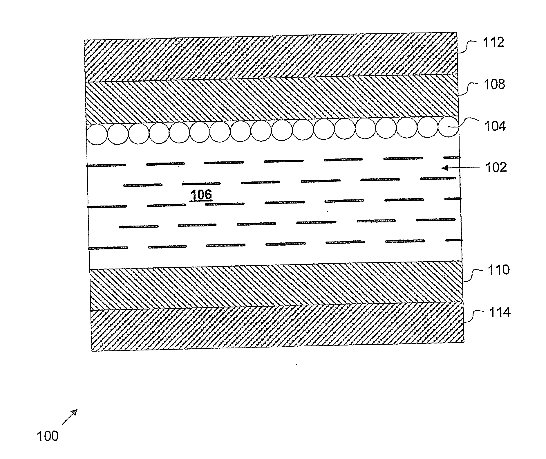
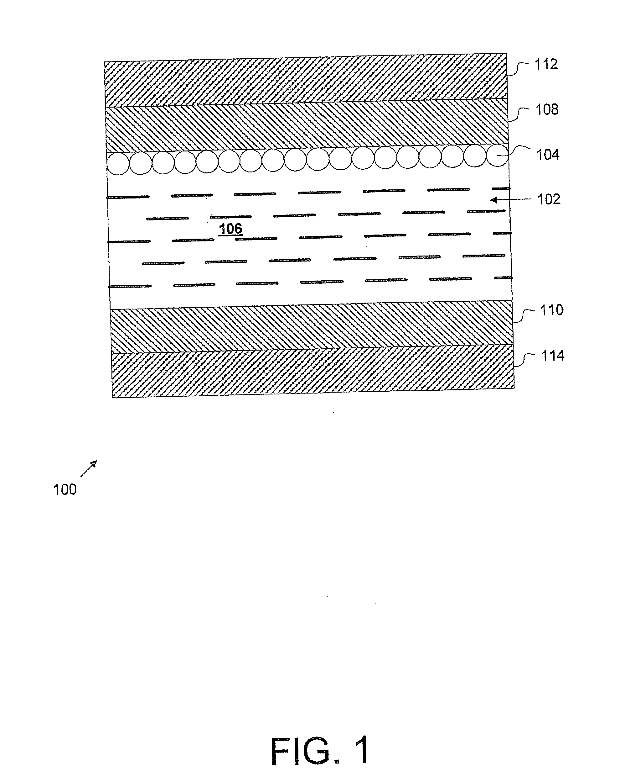
The present invention is about a structure for an EPD module that includes an EPD panel with cells filled with display media and a thermal control pad to control the temperature of the display media. This ensures that the threshold voltage of the cells is at least one-third of the driving voltage needed to achieve the desired display state. The structure may also include a clear front plate, a metal plate, an air gap, a thermal barrier sheet, or an electric power source. The technical effect of this invention is to improve the display quality and reliability of the EPD module.

Problems solved by technology

Cross bias is a well-known problem for a passive matrix display.
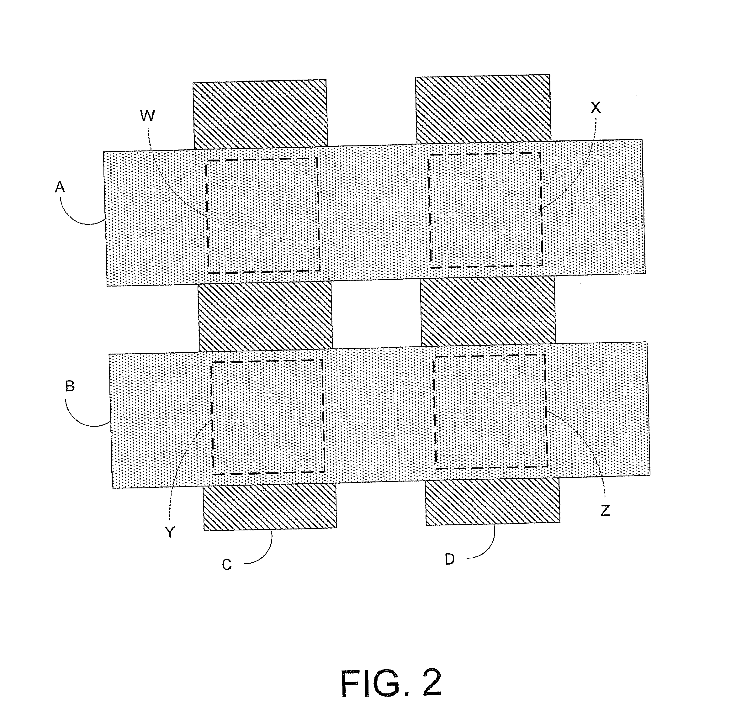
The voltage applied to a column electrode not only provides the driving bias for the cell on the scanning row, but it also affects the bias across the non-scanning cells on the same column.
This undesired bias may force the particles of a non-scanning cell to migrate to the opposite electrode.
This undesired particle migration causes visible optical density change and reduces the contrast ratio of the display.
However, the costs for micro-wire heaters are generally high.
The costs for thin film heaters are also high and such heaters often filter desired light from the display, thus degrading displayed images.

Method used


Image

  • Electrophoretic display with thermal control
  • Electrophoretic display with thermal control
  • Electrophoretic display with thermal control

Examples


Embodiment Construction

[0037]The invention can be implemented in numerous ways, including as a process, an apparatus, a system, a composition of matter, a computer readable medium such as a computer readable storage medium or a computer network wherein program instructions are sent over optical or electronic communication links. In this specification, these implementations, or any other form that the invention may take, may be referred to as techniques. In general, the order of the steps of disclosed processes may be altered within the scope of the invention.

[0038]A detailed description of one or more embodiments of the invention is provided below along with accompanying figures that illustrate the principles of the invention. The invention is described in connection with such embodiments, but the invention is not limited to any embodiment. The scope of the invention is limited only by the claims and the invention encompasses numerous alternatives, modifications and equivalents. Numerous specific details ...


PUM

PropertyMeasurementUnit
temperatureaaaaaaaaaa

Abstract

An electrophoretic display (EPD) with thermal control is disclosed for controlling and maintaining an image in extreme temperature environments. Techniques are also disclosed for maintaining the EPD cell threshold voltage for EPD cells comprising an EPD display media at or above a desired level in an environment in which the EPD may be subjected to an extreme temperature. The techniques comprise sensing a sensed temperature associated with the EPD display media, determining whether the sensed temperature satisfies a criterion established to ensure that the display media temperature remains at a level associated with an acceptable EPD cell threshold voltage, and in the event it is determined that the sensed temperature does not satisfy the criterion, controlling the EPD display media temperature as required to bring the sensed temperature to a level that satisfies the criterion.

Description

[0001]This application is a continuation-in-part of U.S. application Ser. No. 11 / 414,635, filed on Apr. 27, 2006; which is a divisional application of U.S. application Ser. No. 10 / 956,367 filed on Oct. 1, 2004, now U.S. Pat. No. 7,061,662; which claims the benefit of U.S. Provisional Application No. 60 / 509,401 filed on Oct. 7, 2003; the entire contents of all the above-identified applications are incorporated herein by reference in their entirety.RELATED APPLICATIONS[0002]Both U.S. Provisional Patent Application No. 60 / 505,340, entitled “Passive Matrix Electrophoretic Display Driving Scheme,” filed May 16, 2003; and co-pending U.S. Patent Application Publication No. US 2004-0246562, entitled “Passive Matrix Electrophoretic Display Driving Scheme,” filed Apr. 30, 2004; are incorporated herein by reference in their entirety.FIELD OF INVENTION[0003]The present invention relates generally to display devices. More specifically, an electrophoretic display with thermal control is disclosed...

Claims


Application Information

Patent Timeline
Patent Type & Authority Applications(United States)
IPC IPC(8): G09G3/34G02F1/167G02F1/1675
CPCG02F1/133382G02F1/167G02F1/133385G02F1/1675
Inventor CHUNG, JERRYLIANG, RONG-CHANGSPRAGUE, ROBERT A.
Owner E INK CORPORATION
Learn More