Development device and image forming apparatus comprising same

Inactive Publication Date: 2008-09-11
SHARP KK
View PDF12 Cites 9 Cited by
  • Summary
  • Abstract
  • Description
  • Claims
  • Application Information

AI Technical Summary

Benefits of technology

[0014]The first object of the present invention is to provide a development device which can unfailingly shut the supply opening of the toner supply device for a long term, and to provide an image forming apparatus equipped with such a development device. The

Problems solved by technology

However, the carrier deteriorates by being used, therefore after a certain period passes from the start of use, maintenance to replace the two component developer in the development tank with a new two component develope

Method used


Image

  • Development device and image forming apparatus comprising same
  • Development device and image forming apparatus comprising same
  • Development device and image forming apparatus comprising same

Examples


first embodiment

[0042]One embodiment of the present invention referring to FIGS. 1 to 11 is described below. The embodiment described below is one detailed example of the present invention, and does not limit the scope of the present invention.

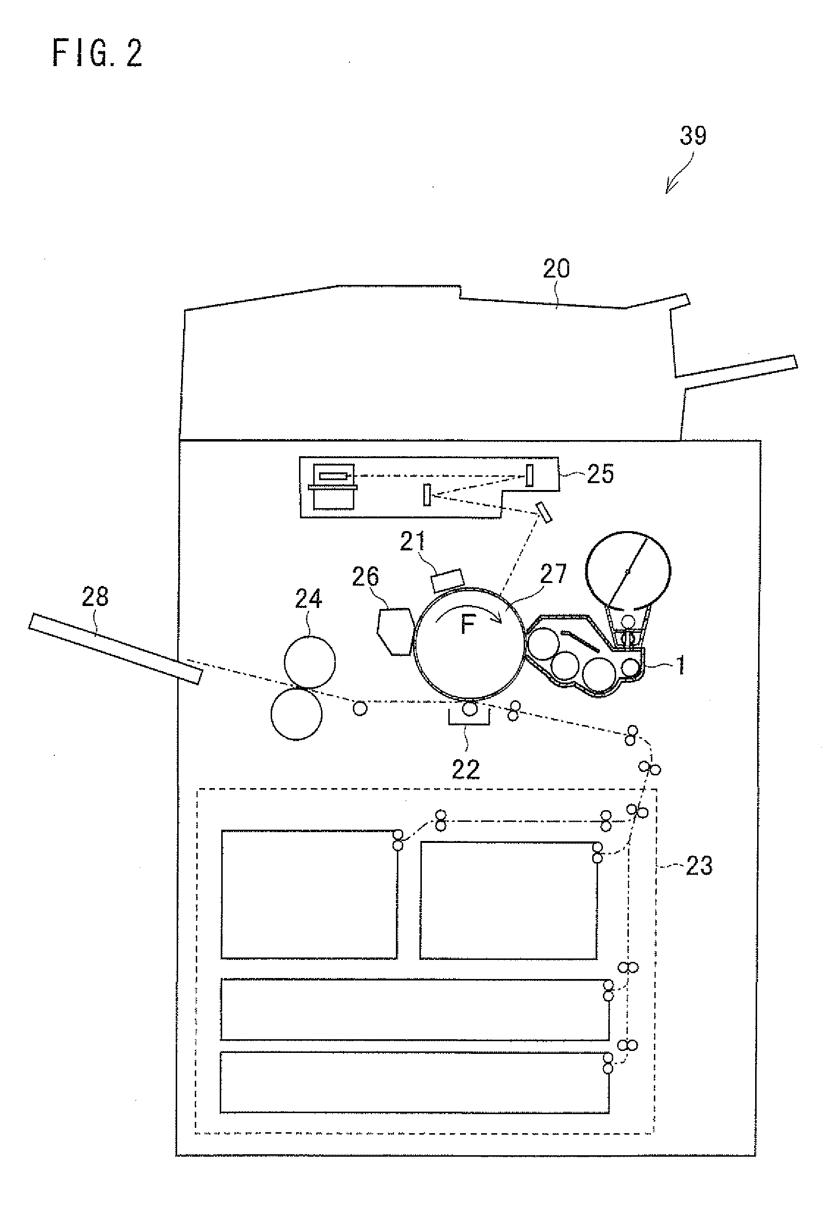
[0043]Firstly the overall structure of an image forming apparatus 39 of an electrophotography printing method is described referring to FIG. 2. The image forming apparatus 39 includes a development device 1 in one embodiment. FIG. 2 is a brief explanation view of the overall structure of the image forming apparatus 39.

[0044]The image forming apparatus 39 includes a photoreceptor 27. A charging device 21, an exposure device 25, a development device 1, a transfer device 22 and a cleaning device 26 are arranged around the photoreceptor 27.

[0045]The photoreceptor 27 is of a drum-shape having a photoconductive material on its surface, and is rotated in a direction indicated by the arrow F. The charging device 21 evenly (uniformly) charges the surface of the photor...

second embodiment

[0107]The following is an explanation of another embodiment of the present invention, referring to FIGS. 12 to 15. As a matter of convenience in explanation, members with the same functions as the members used in the First Embodiment have the same reference codes, and the explanations of those is omitted here.

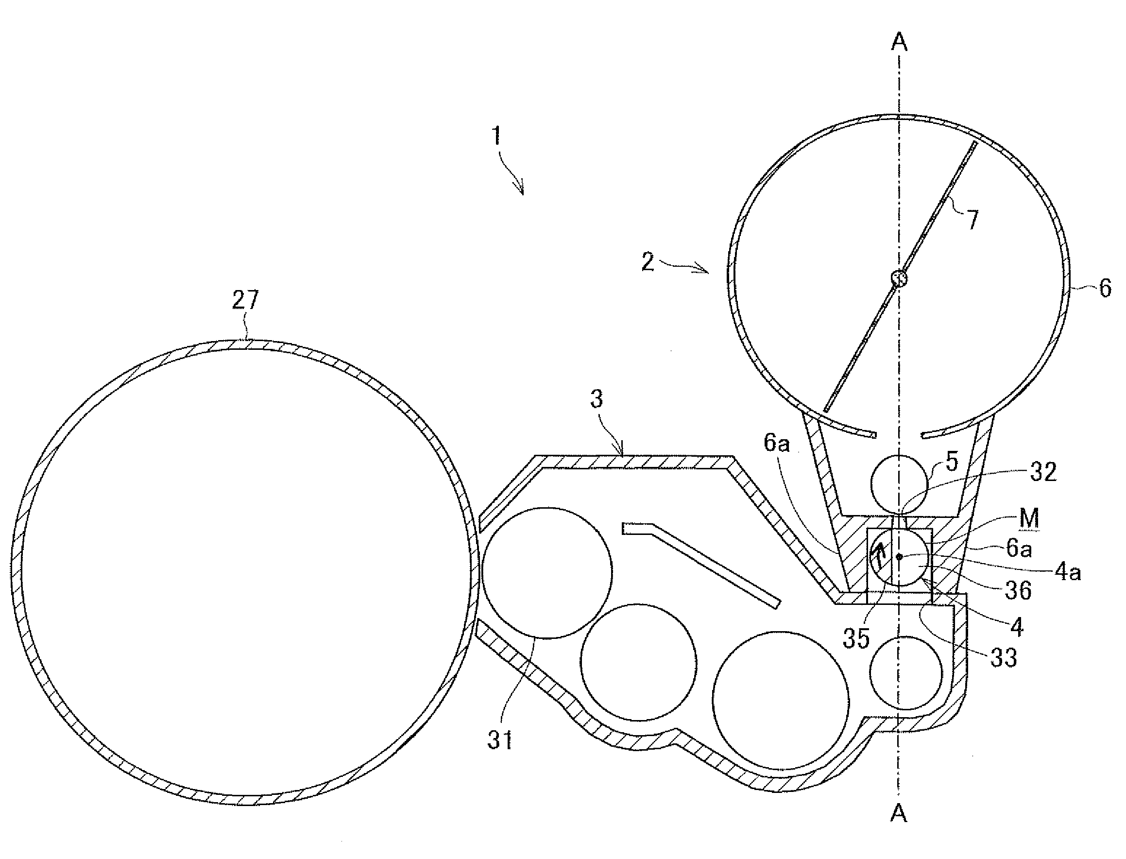
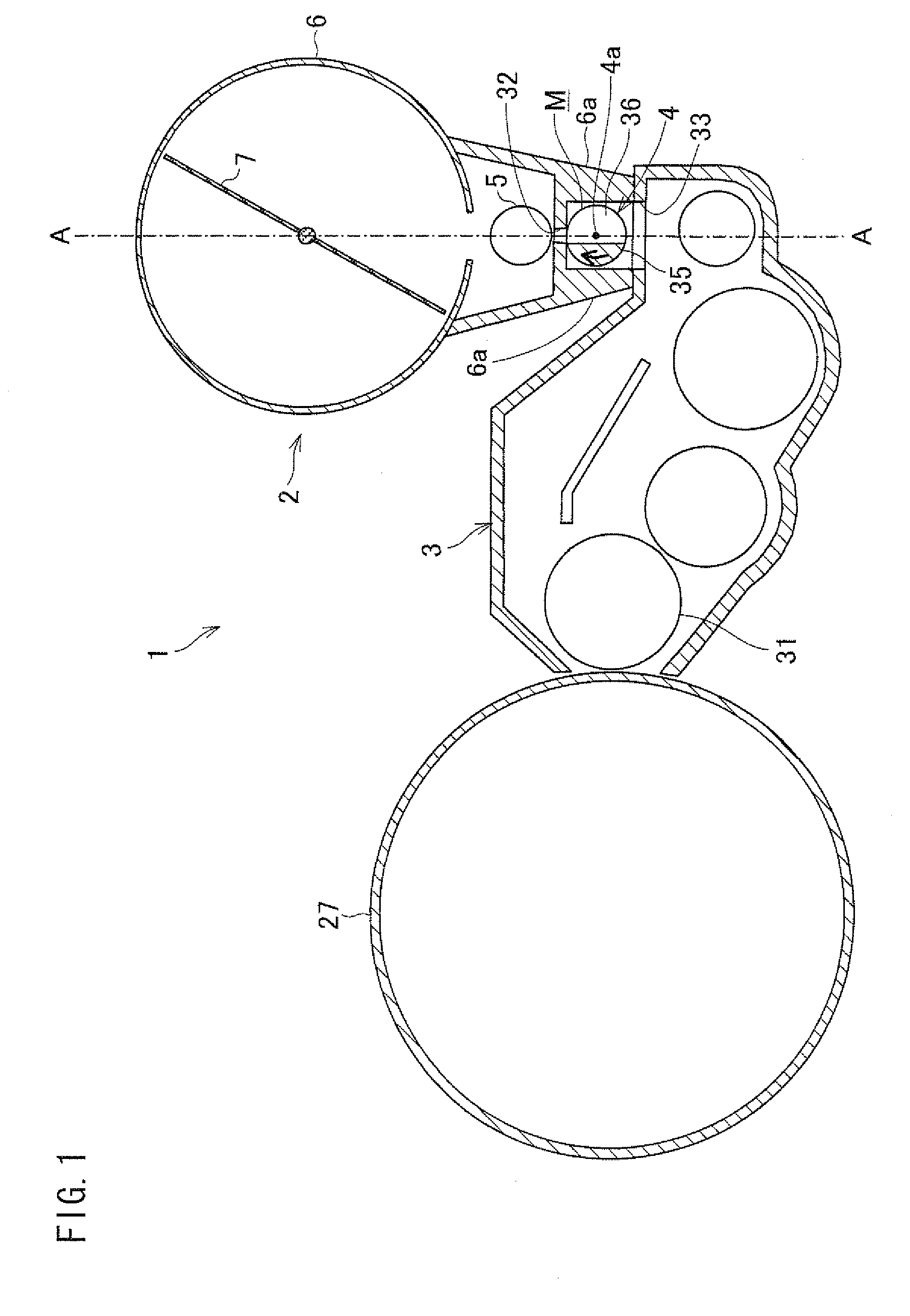
[0108]FIG. 12 is a front sectional view illustrating the structure of a development device 57 of the present embodiment. The difference between the development device 57 and the development device 55 in the aforementioned FIG. 10 is a discharge opening 56 provided in the communicating chamber M. The development device 57 has a blocking wall 6b in the communicating chamber M, located in the vicinity of the receiving opening 33, blocking the communicating chamber M from the receiving opening 33. The discharge opening 56 is formed on the blocking wall 6b. The communicating chamber M communicates to the developing tank 3 through the discharge opening 56 and the receiving opening 33...


PUM


Abstract

The development device of the present invention has a rotating shutter supported rotatably between a supply opening formed on a toner supply device and a receiving opening formed on a developing tank. The rotating shutter has an open section extending in the axial direction of the roller-shaped main section as well as opened in the direction perpendicular to the axial direction thereof, opening and shutting the supply opening in conjunction with attachment and detachment operation of the developing tank. The rotating shutter shuts the supply opening by covering the supply opening with the outer surface of the roller-shaped main section, and opens the supply opening by communicating the supply opening and the receiving opening through the open section. Thus, it is possible to prevent the leakage of toner even after repetitively performing the attachment and detachment operation of the developing tank.

Description

[0001]This Nonprovisional application claims priority under 35 U.S.C. §119(a) on Patent Application No. 059169 / 2007 filed in Japan on Mar. 8, 2007, the entire contents of which are hereby incorporated by reference.FIELD OF THE INVENTION[0002]The present invention relates to a development device used in an image forming apparatus such as an electrostatic copier, a laser printer, or a facsimile, and an image forming apparatus, each of which includes such a development device. More precisely, the present invention relates to a development device using a two component developer including toner and carrier, and an image forming apparatus equipped with such a development device.BACKGROUND OF THE INVENTION[0003]In an image forming apparatus using an electrophotographic printing method, image-forming is performed such that an electrostatic latent image is formed on a photoconductive drum, toner is then adhered to this latent image, thereby to form a toner image therefrom, and the toner imag...

Claims


Application Information

Patent Timeline
IPC IPC(8): G03G15/08
CPCG03G2215/067G03G15/087G03G15/0886
Inventor KIMURA, TAKAHIKOHAYASHI, SHIGEKIAKEDO, SHUICHISUDOH, TERUYOSHIUSUI, TOMOYA
Owner SHARP KK
Why Eureka
Try Eureka