Fluorescence detection apparatus

a fluorescence detection and apparatus technology, applied in the field of analysis techniques, can solve the problems of difficult movement of the sample substrate, inability to clean the apparatus, and inability to achieve the effect of improving the operation

Inactive Publication Date: 2010-07-06
HITACHI HIGH-TECH CORP
View PDF3 Cites 5 Cited by
  • Summary
  • Abstract
  • Description
  • Claims
  • Application Information

AI Technical Summary

Benefits of technology

[0011]The present invention relates to an analysis technique for qualitatively detecting or quantifying biomolecules by producing an evanescent field on a surface of a substrate, exciting fluorescently labelled biomolecules on the substrate surface in the evanescent field, and detecting the resultant fluorescence emitted from the biomolecules, and a well is provided in a surface opposing a sample substrate, and the matching liquid is filled in the well so as to involve the sample substrate in the matching liquid and fill the matching liquid between the sample substrate and the prism, thereby overcoming the above problem.
[0012]By providing the well in the surface opposing the sample substrate of the prism, it is possible to prevent the matching liquid from being leaked out and preventing an excitation light incidence surface of the prism or an apparatus from being dirty by the leaked matching liquid. In addition, since the well can be filled with the matching liquid by simply pouring the matching liquid into the well, operability can be improved.

Problems solved by technology

In this case, however, if the amount of the flown matching liquid is excessive, an apparatus may become dirty due to matching liquid leaked out during replacement of the sample substrate or the like, which may have an adverse effect on stage precision or measurement.
In this case, if the amount of flown matching liquid is small, it becomes difficult for the sample substrate to move due to surface energy of the matching liquid.
On the other hand, if the amount of flown matching liquid is excessive, an apparatus becomes dirty not only during replacing the sample substrate, but also when the sample substrate moves as the prism is pressed against the sample substrate.
In addition, in the method disclosed in JP-A-8-136554, if the amount of flown matching liquid is excessive, when the prism is pressed against the sample substrate or is moved with respect to the sample substrate, the matching liquid flows into the oil puddle and thus the matching liquid between the prism and the sample substrate becomes insufficient, thereby causing air to be easily introduced therebetween.
Accordingly, since it is required to pay attention to the amount of filling of the matching liquid and the movement of the sample substrate, the disclosed method has a problem of operability as a whole.
In this manner, the above-described conventional techniques have insufficient consideration of a structure of an apparatus with good operability which is capable of producing a stable evanescent field.

Method used


Image

  • Fluorescence detection apparatus
  • Fluorescence detection apparatus
  • Fluorescence detection apparatus

Examples


embodiment 1

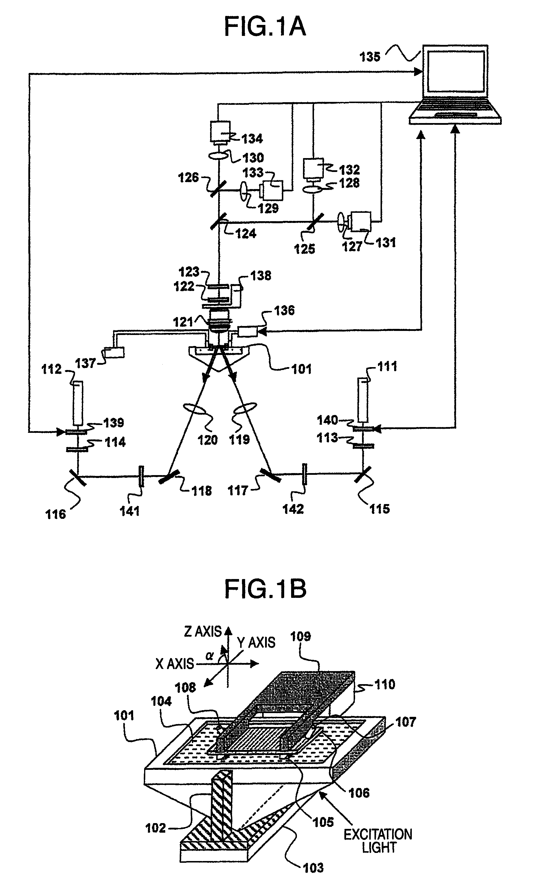
[0039]FIG. 1A is a view illustrating a configuration of Embodiment 1 according to the invention. FIG. 1B is an enlarged perspective view showing a prism 101 and its vicinity.

[0040]A prism 101 provided with a well is, for example, made of S-BAL14 and has three 60° equilateral surfaces each having a size of 60 mm×50 mm. An acryl frame having height of about 8 mm (depth of the well later), as a wall of the well, is adhered to one (surface opposed to a sample substrate 106) of the three surfaces. Aside from the above-described method, a well structure may be prepared by cutting a surface of the prism 101.

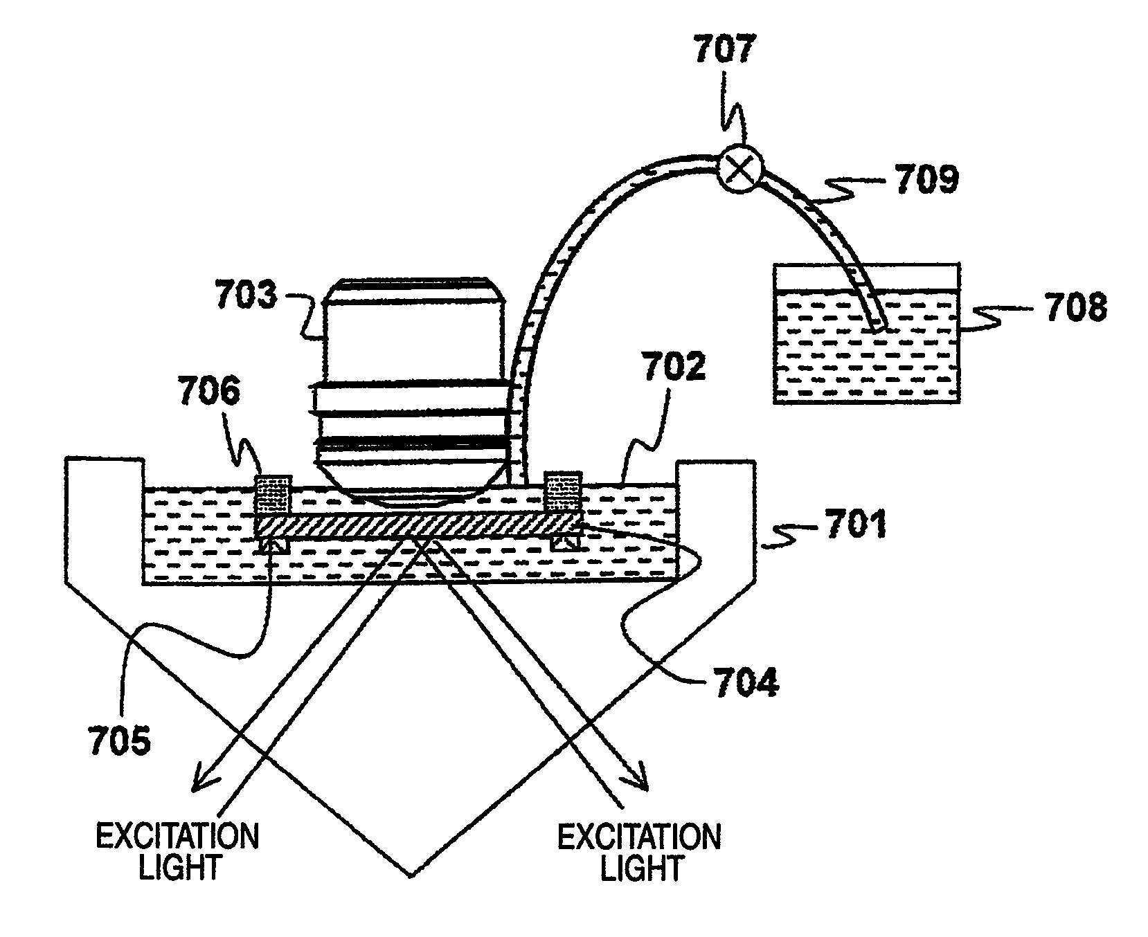
[0041]Height of the well is required to be adjusted such that a surface of the sample substrate 106 including a sample supporting member 105 which opposes the prism 101, can be immersed in a matching liquid 104. Instead of S-BAL14, the material of the prism may be glass such Bak4, quartz or the like, resin such as PDMS or the like, or other materials as long as they have low absorptiven...

embodiment 2

[0068]Next, Embodiment 2 shows an example of measurement by a high aperture-oil immersion type objective lens.

[0069]A fluorescent signal from a single fluorescent molecule is weak. Thus, if a background is high or noise derived from an apparatus is large, it is difficult to detect emission bright spots. Therefore, detecting means having higher sensitivity, such as an objective lens with high numerical aperture, is required.

[0070]However, since an objective lens with numerical aperture of 1.3 or above is required to be used in an oil immersion state, there is a need to fill the immersion oil between a sample substrate and the objective lens. At that time, operability is poor, immersion oil flows around to make an apparatus dirty, or it takes a long time for a filling operation. Further, when the determination in Embodiment 1 is automated, an immersion oil filling device is required, thereby increasing the burden in terms of space and cost.

[0071]Embodiment 2 of the present invention p...

embodiment 3

[0076]In Embodiment 1, the excitation light sources 111 and 112 are provided in different light paths and the excitation light is incident from both sides of the prism 101, as shown in FIG. 1A. If a dichroic mirror 1602 is placed before a mirror 1601 and it is possible to make excitation light paths from two light sources 1603 and 1604 equal, as shown in FIG. 16, it is possible to reduce costs of optical components such as a condensing lens 1609, mirrors and so on and make an apparatus compact.

[0077]However, if the excitation light is incident from the same plane of a prism 1605 with the above equal light paths, deviation of a position of evanescent irradiation from light sources having different wavelengths increases due to a refraction angle difference at an interface between the prism 1605 and the matching liquid 1606 depending on a wavelength, along with a distance between the sample substrate 1607 and the prism 1605.

[0078]FIG. 17A illustrates respective light paths of when exci...


PUM


Abstract

A fluorescent detection apparatus relates to an analysis technique for qualitatively detecting or quantifying biomolecules by producing an evanescent field on a surface of a substrate, exciting fluorescently labelled biomolecules on the substrate surface in the evanescent field, and detecting the resultant fluorescent light emitted from the biomolecules. The fluorescent detection apparatus has a configuration in which a well is provided in a surface opposing to a sample substrate of a prism, the well is filled with a matching liquid, and the matching liquid is filled between the sample substrate and the prism, thereby improving operability and providing a stable evanescent field.

Description

INCORPORATION BY REFERENCE[0001]The present application claims priority from Japanese application JP2007-335612 filed on Dec. 27, 2007, the content of which is hereby incorporated by reference into this application.FIELD OF THE INVENTION[0002]The present invention relates to an analysis technique for qualitatively detecting or quantifying biomolecules by producing an evanescent field on a surface of a transparent substrate, exciting fluorescently labelled biomolecules in a liquid sample supplied on the substrate surface in the evanescent field, and detecting the resultant fluorescent light emitted from the biomolecules.DESCRIPTION OF RELATED ART[0003]In the related art, single fluorescent molecule has been observed using an evanescent field produced on a substrate surface by irradiating excitation light emitted from an light source to a transparent sample substrate and totally reflecting the excitation light on the surface of the sample substrate.[0004]For example, as disclosed in “...

Claims


Application Information

Patent Timeline
Patent Type & Authority Patents(United States)
IPC IPC(8): G01J3/30
CPCG01N21/6428G01N21/648
Inventor HAGA, TAKANOBUTAKAHASHI, SATOSHIKUMAZAKI, NOBUTAKAKATO, HIROKAZUSONEHARA, TSUYOSHI
Owner HITACHI HIGH-TECH CORP
Why Eureka
Try Eureka