
Image forming apparatus and image forming method

an image forming apparatus and image technology, applied in the direction of electrographic process apparatus, instruments, optics, etc., can solve the problems of reducing the efficiency of toner collection, affecting the quality of toner, so as to prevent paper sheets from being stained, adjust patterns easily and inexpensively

Inactive Publication Date: 2008-09-18
RICOH KK
View PDF3 Cites 27 Cited by
  • Summary
  • Abstract
  • Description
  • Claims
  • Application Information

AI Technical Summary

Benefits of technology

[0010]The present invention addresses the above-mentioned conventional problems. It is an object of the present invention to provide an image forming apparatus and an image forming method that can prevent paper sheets from being stained due to adjustment patterns easily and inexpensively.
[0021]According to the embodiments of the present invention, even if the density adjustment pattern or the position adjustment pattern becomes attached to the secondary transferring member, the stain prevention pattern consisting of yellow toner is further attached on the density adjustment pattern or the position adjustment pattern as attached. Since the yellow toner stain prevention pattern is unnoticeable or rarely recognized for white sheets, it is possible to prevent the sheets from being stained. In addition, the present invention is advantageous to prevention of the edge of sheet from being stained, resulting in the high quality of the sheet being maintained.

Problems solved by technology

However, it is impossible to deliver the toner to the intermediate transferring body completely even through intensive operations of the electric field.
When the weakly charged toner and / or the non-charged toner is attached to the secondary transferring member, it is hard to move the toner to the intermediate transferring body even through electrostatic application of an electric field, and thus the back surface of a sheet may be stained during passage.
In addition, Japan Laid-Open Patent Application No. 2004-272206 does not take environmental variations into consideration, and thus if the environment varies, the optimum cleaning bias is not applied to the secondary transferring member, resulting in reduced efficiency of the toner collection.

Method used


Image

  • Image forming apparatus and image forming method
  • Image forming apparatus and image forming method
  • Image forming apparatus and image forming method

Examples


Embodiment Construction

[0030]Embodiments of the present invention will be described below with reference to the accompanying drawings.

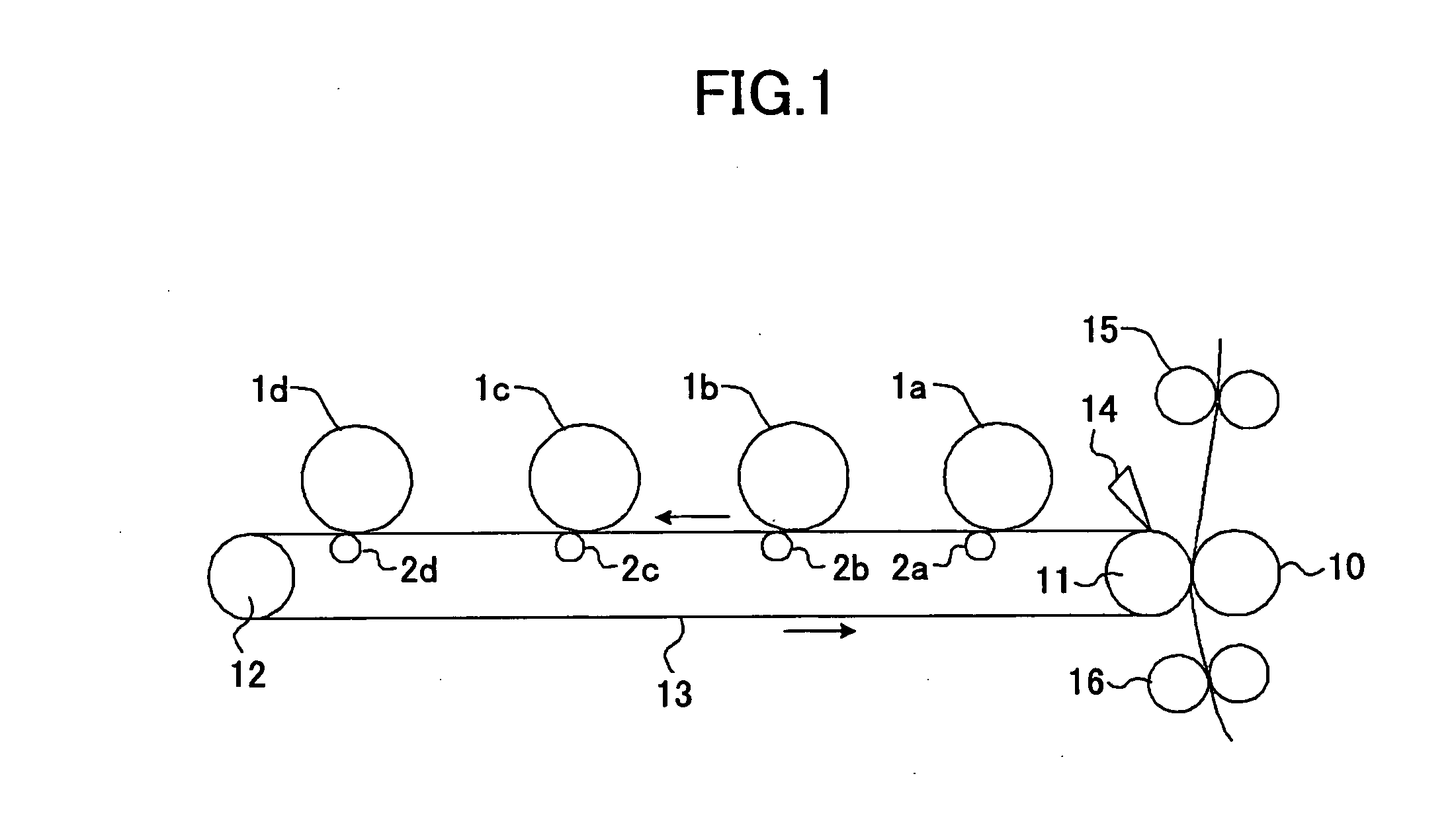
[0031]FIG. 1 is a schematic view of core components of an image forming apparatus according to one embodiment of the present invention. In this embodiment, the image forming apparatus is a color image forming apparatus capable of forming full color images in a tandem fashion. In the image forming apparatus, four imaging units having respective photoconductive drums 1a-1d serving as image carriers are provided along the top surface of an intermediate transferring belt serving as an intermediate transferring body. Although omitted in the illustration for clarity, in each of the imaging units, an electrifying unit, a developing unit, a cleaning unit and others are disposed around the respective photoconductive drums 1a-1d. Furthermore, transferring rollers 2a-2d are provided as primary transferring units within the intermediate transferring belt 13 to face the respective photo...


PUM


Abstract

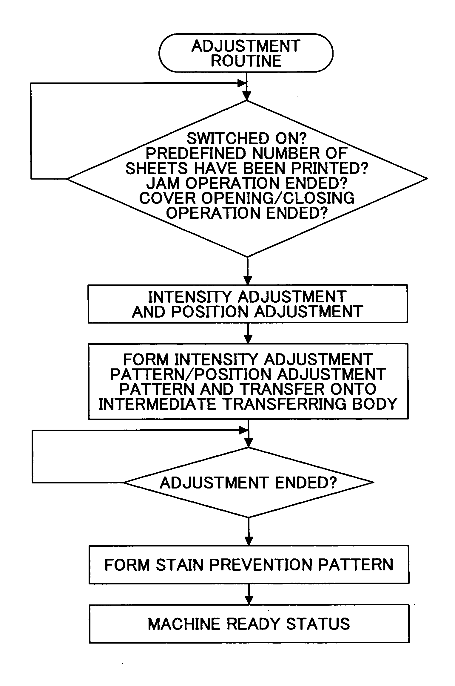
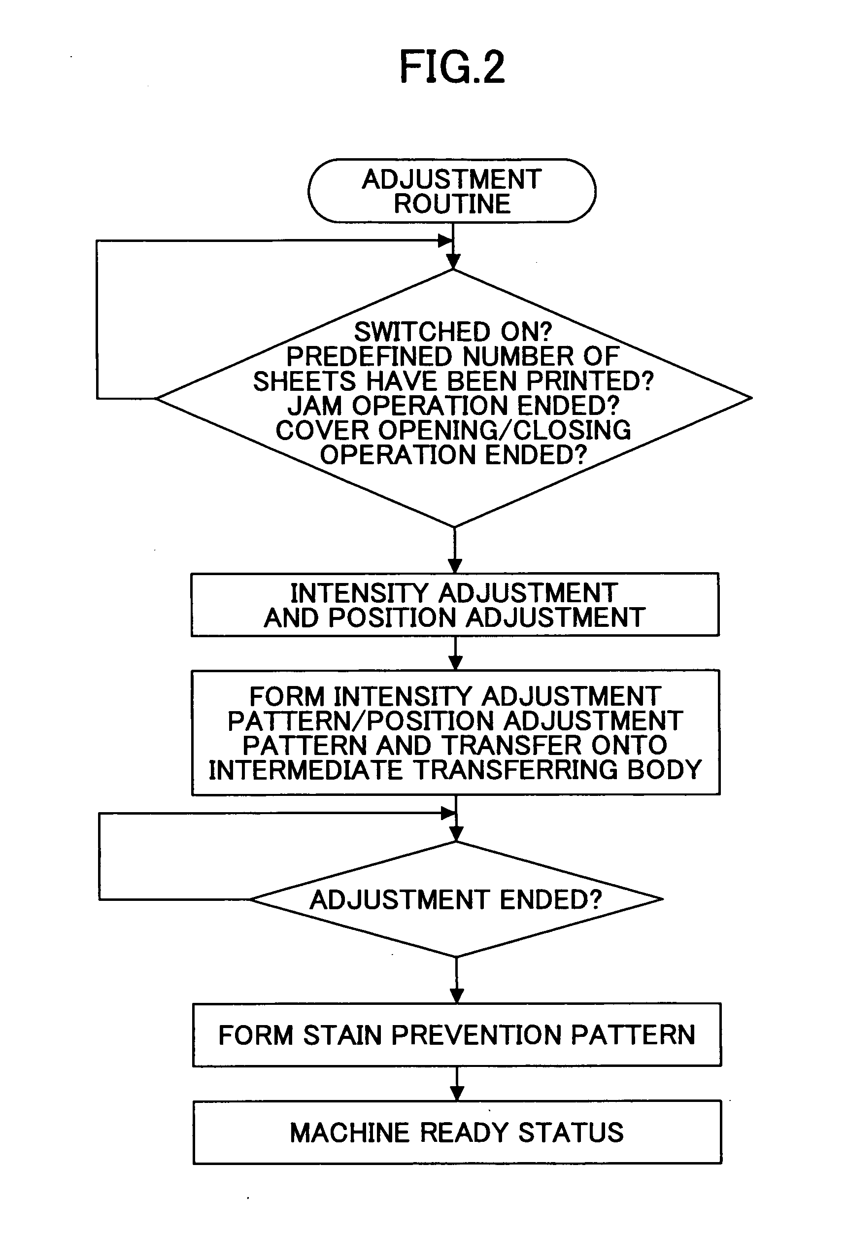
An image forming apparatus includes an image carrier, an intermediate transferring body and a contact type secondary transferring member transferring an image from the intermediate transferring body to a recording medium. The apparatus forms an image with respective developers for multiple colors and uses a predefined adjustment pattern to make density adjustment and position adjustment of respective color images. After execution of the density adjustment and / or the position adjustment, a stain prevention pattern is formed with a yellow developer to cover an area where the adjustment pattern is attached to the secondary transferring member.

Description

BACKGROUND OF THE INVENTION[0001]1. Field of the Invention[0002]The present invention relates to an electrophotographic image forming apparatus and an image forming method thereof, and particularly relates to some techniques for preventing the back surface and edges of sheets from being stained in the secondary transferring unit.[0003]2. Description of the Related Art[0004]Currently, the most prevalent type of color image forming apparatus employs an intermediate transferring body. Individual color images formed on respective image carriers are sequentially superimposed and transferred onto the intermediate transferring body (belt), and then the superimposed and transferred images are transferred together onto a sheet. In such an image forming apparatus, a secondary transferring member (roller) in contact with the back surface of a sheet is often used to transfer multiple color toner images onto the sheet together.[0005]Also in cases of color printers or color copiers, the density a...

Claims


Application Information

Patent Timeline
Patent Type & Authority Applications(United States)
IPC IPC(8): G03G15/00G03G15/16G03G15/01
CPCG03G15/0131G03G2215/00059G03G15/161G03G2215/1652G03G2215/0161
Inventor TSUCHIDA, YOSHIEMIYAZAKI, TAKAFUMI
Owner RICOH KK
Learn More