
Disposable, floating, flame heated wax melting plate for confined and unconfined conventional candles and attachment method for use in candle making

Inactive Publication Date: 2008-09-18
KITT STEVE B
View PDF8 Cites 10 Cited by
  • Summary
  • Abstract
  • Description
  • Claims
  • Application Information

AI Technical Summary

Benefits of technology

[0030](a) To provide an economical or low cost solid wax heat conductive melting plate consisting of one part having a centrally located wick receiving hole therethrough.
[0040](k) To provide a heat conductive melting plate wherein the outer diameter attaching means is wider in plates made for larger confined and unconfined conventional candles, this attaching means sinking into the wax when the plate is heated, wherein the heated wax covering over said attaching means acts as an insulator limiting heat loss to the surrounding air making the plate easier to keep hot at greater distance from the limited heat source of the candles flame.

Problems solved by technology

This device contains many costly parts and is made for use in confined candles only and further is not made for use on or in confined or unconfined conventional candles having their own wick.
The flame provided from most conventional candles is a very limited heat source for heating of such large diameter melting plates.
Thirdly it is very difficult to heat a larger mass of metal such as two plates than it is to heat a single plate to a temperature sufficient to melt wax from such a limited heat source such as the candle flame.
They are designed with a drip edge to fit over the outside diameter of an unconfined conventional candle, further limiting their use on both types of conventional candles, confined and unconfined.
Glass is heavy, if sat on the top surface of the wax it would quickly sink into the wax loosing its ability to trap the much needed radiant heat between the underside of the glass and the wax surface and would no longer function.
Bormann uses glass due to its poor heat retention qualities limiting the use of direct heat attainable from the flame to be conducted therefrom into a conductive plate such as aluminum and into the surrounding wax.

Method used


Image

  • Disposable, floating, flame heated wax melting plate for confined and unconfined conventional candles and attachment method for use in candle making
  • Disposable, floating, flame heated wax melting plate for confined and unconfined conventional candles and attachment method for use in candle making
  • Disposable, floating, flame heated wax melting plate for confined and unconfined conventional candles and attachment method for use in candle making

Examples


Embodiment Construction

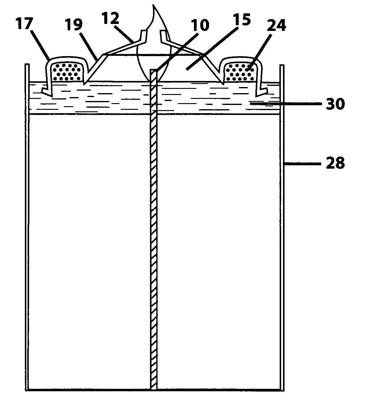
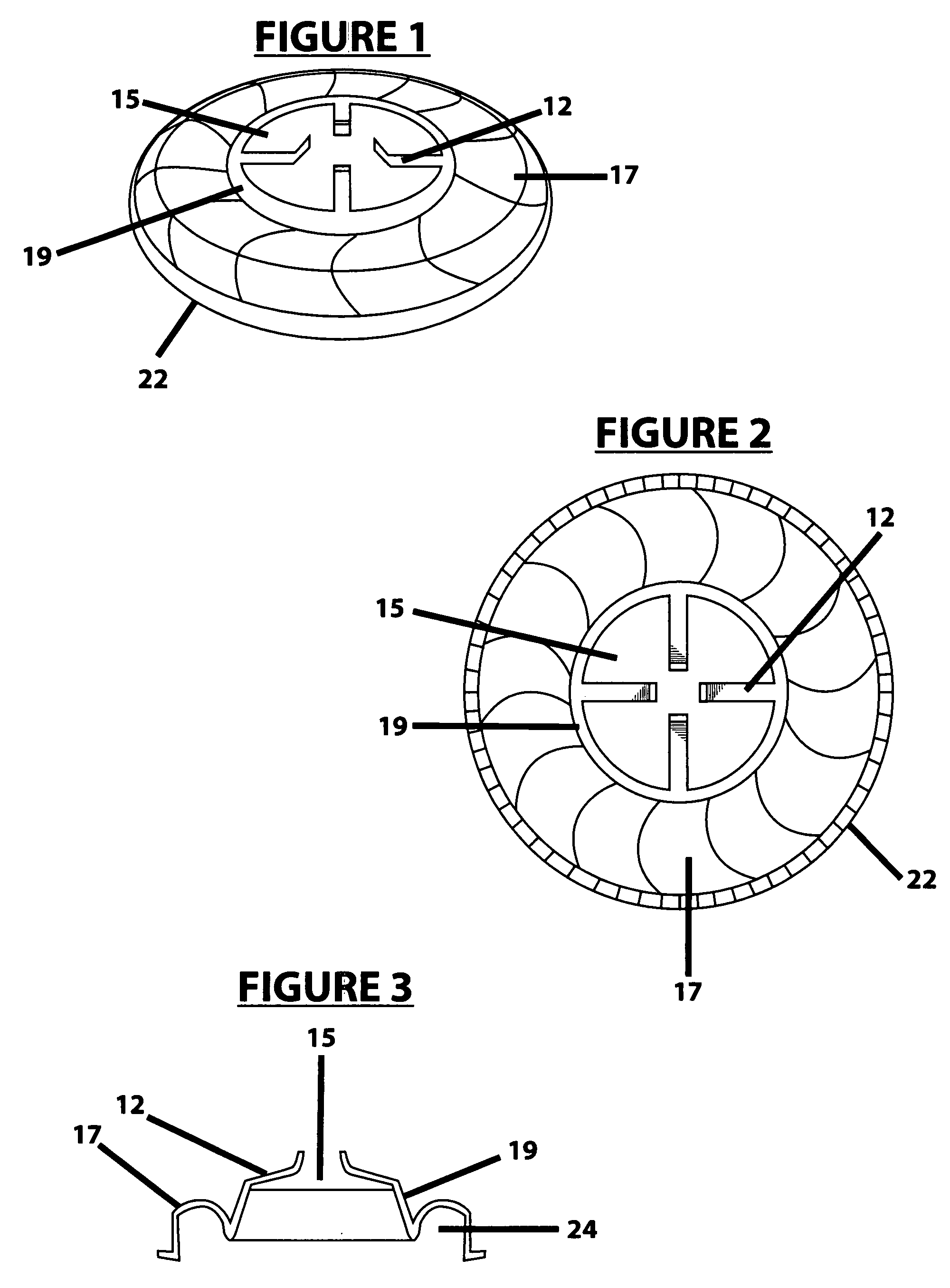
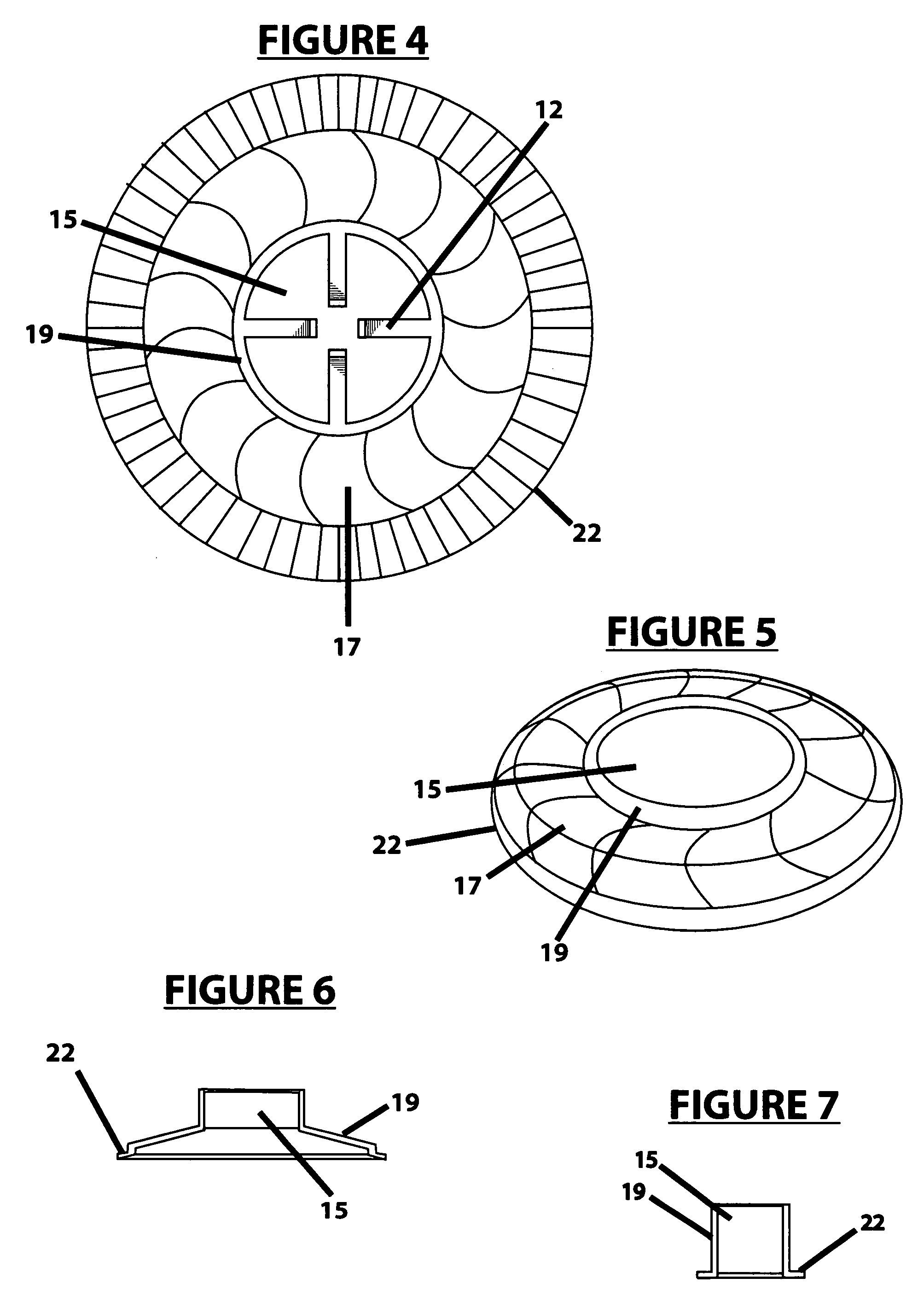
[0056]The above-described drawings show the preferred melting plates that are versatile and interchangeable to both confined and unconfined conventional candles. The processes used to make the plate, such as die-cutting, bending or molding is well known in the manufacturing field of like products. Therefor the plate is made as shown in the drawings. The drawings are scaled drawings showing the exact dimensions of the preferred melting plates. The plate is formed from a heat conductive material such as aluminum having a centrally located wick receiving hole therethrough. The inventor has made and used the invention in various forms and finds it functions and operates very well in structures shown herein.

[0057]Referring to the drawings wherein like numerals indicate like portions throughout the different views, one such plate the preferred floating plate in FIG. 1 completely surrounds the wick receiving hole 15, an attaching means portion 22 bent in the outer diameter of the plate 90 ...


PUM


Abstract

A disposable floating flame heated candle following melting plate for melting the wasted solid wax in confined and unconfined conventional candles to a liquid form sufficient to cause the wax to flow back to the candle flame for consumption, wherein the improved plate is a single plate structure capable of floating, plate structure having an attaching method for use in the candle making process and attaches itself to a candle when marketed separate from its fuel source or candle.

Description

FIELD OF THE INVENTION[0001]The present invention relates to flame heated candle wax melting plates which follow confined and unconfined conventional candles downwardly during there burning and possesses superior qualities to enable the single plate to float, heat quickly, retain and distribute said heat at a greater distance from the the candle flame and is interchangeable between unconfined and confined conventional candles and more particularly to disposable floating flame heated solid wax melting plates formed in manufacture having only one part and a method of attaching the plate to the candle in the candle building process.BACKGROUND OF THE INVENTION[0002]Flame heated melting plates or apparatus candle wax melting devices for following the melting of the candle downwardly have long been used for melting to a liquid, that wax furthest from the candle flame that otherwise would not be melted by the flame, to a liquid form sufficient enough to cause flow of the liquid wax back to...

Claims


Application Information

Patent Timeline
IPC IPC(8): F23D3/16
CPCF23D3/26F23D3/16
Inventor KITT, STEVE B.
Owner KITT STEVE B
Learn More