
Hydraulic disc brake device

a technology of hydraulic disc brakes and brake pads, which is applied in the direction of braking systems, cycle equipments, cycle brakes, etc., can solve the problems of sudden deadlock, skidding or overturning of vehicles, and conventional hydraulic disc brake devices, and achieve the effect of low cost and economics

Inactive Publication Date: 2009-11-10
HUANG TAN CHENG
View PDF3 Cites 0 Cited by
  • Summary
  • Abstract
  • Description
  • Claims
  • Application Information

AI Technical Summary

Benefits of technology

[0007]The primary objective of the present invention is to provide a hydraulic disc brake system that has an antilock effect.
[0008]The secondary objective of the present invention is to provide an economical and low cost hydraulic disc brake system for a vehicle, without needing any precision electronic instruments or electric mechanism.

Problems solved by technology

However, these conventional hydraulic disc brake devices still have the following disadvantages:
The clamping force caused by the oil pressure in the case of an emergency brake is always very great, and the resultant braking force will be excessively large, and thus probably causing a sudden dead lock.
As a result, not only will the tire be locked, but also the vehicle will suffer an instant run-out, leading to a skidding or overturning of the vehicle.

Method used


Image

  • Hydraulic disc brake device
  • Hydraulic disc brake device
  • Hydraulic disc brake device

Examples


second embodiment

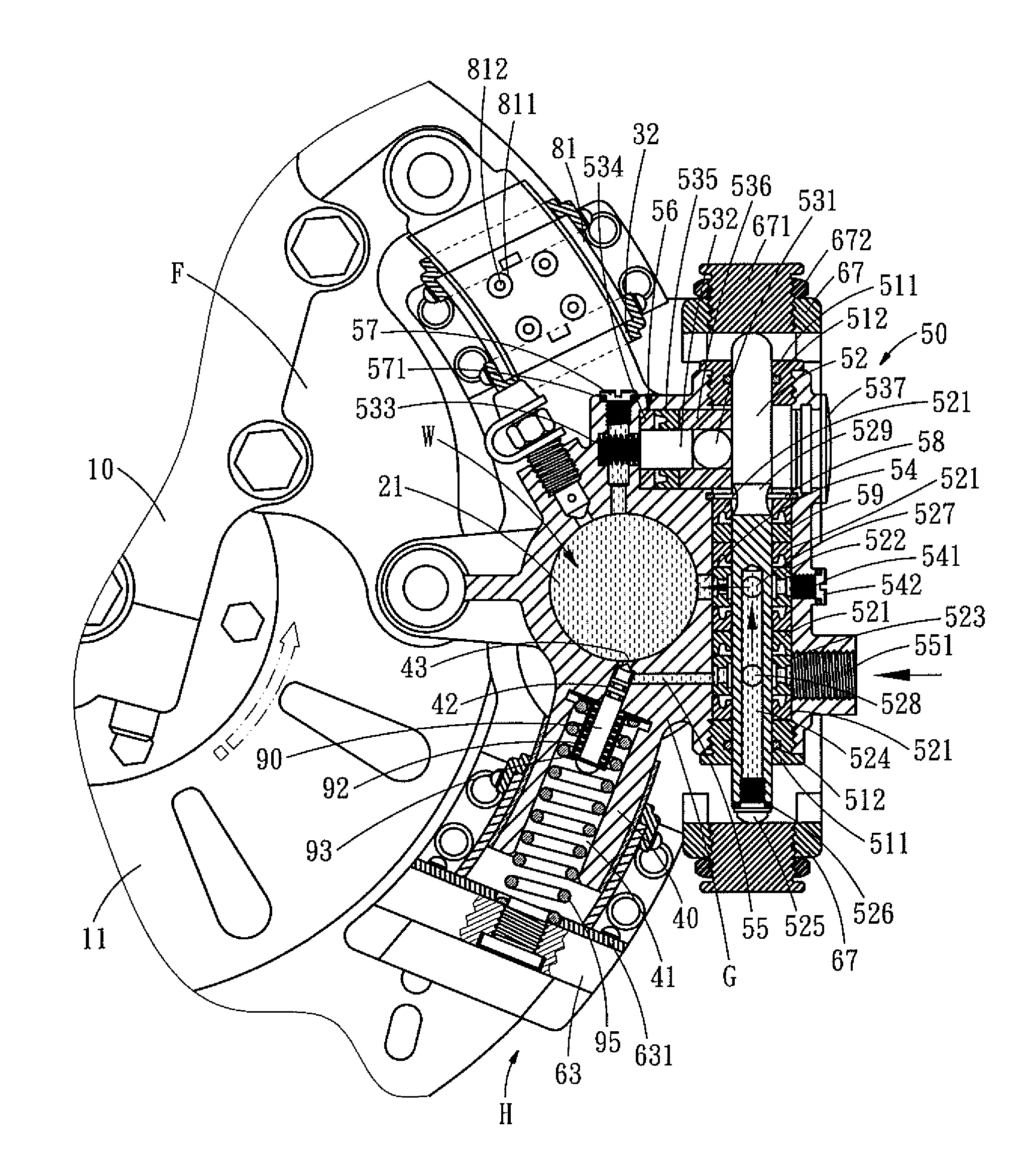
[0049]Referring to FIGS. 8 and 9, which show a In this embodiment, there are two sets of oil chambers 21, pistons 22 and steel-ball positioning discs 25, and each set includes the oil seals 23, 23a, 24, 24a, steel-ball positioning discs 25, 25a, a plurality of steel balls 26, 26a, and pistons 22, 22a slideably sealed in two oil chambers 21, 21a. The two oil chambers 21 are in communication with each other via a main passage 54. An exhaust valve 27 is arranged beside the oil chamber 21, and a safety oil passage 43 is formed beside the oil chamber 21a. By using the double pressing devices 20, the resultant braking force will be more strong, and the antilock effect will be better.

third embodiment

[0050]FIG. 10 shows the present invention, this embodiment is additionally provided with a main cylinder C3 and an elastic oil-storage cylinder C31. The seat C1 is installed on the wheel carrier 10 and serves to cooperate with the moveable base assembly C2. The status of the hydraulic disc brake device before braking action is shown in FIGS. 11-14, the status of the hydraulic disc brake device during braking action is shown in FIGS. 15-18, and the status of the hydraulic disc brake device during antilock action is shown inFIGS. 19-21.

[0051]The seat C1 is fixed onto the wheel carrier 10, a L-shaped stop board C11 is riveted to either side of the seat C1, and a space is defined between the two L-shaped stop boards C11. The two L-shaped stop boards C11 are located in the arc-shaped route of the wheel axis. Two sliding members C12 with opening facing each other are disposed in the arc-shaped route of the wheel axis, and each of the sliding members C12 is a structure with one end closed ...


PUM


Abstract

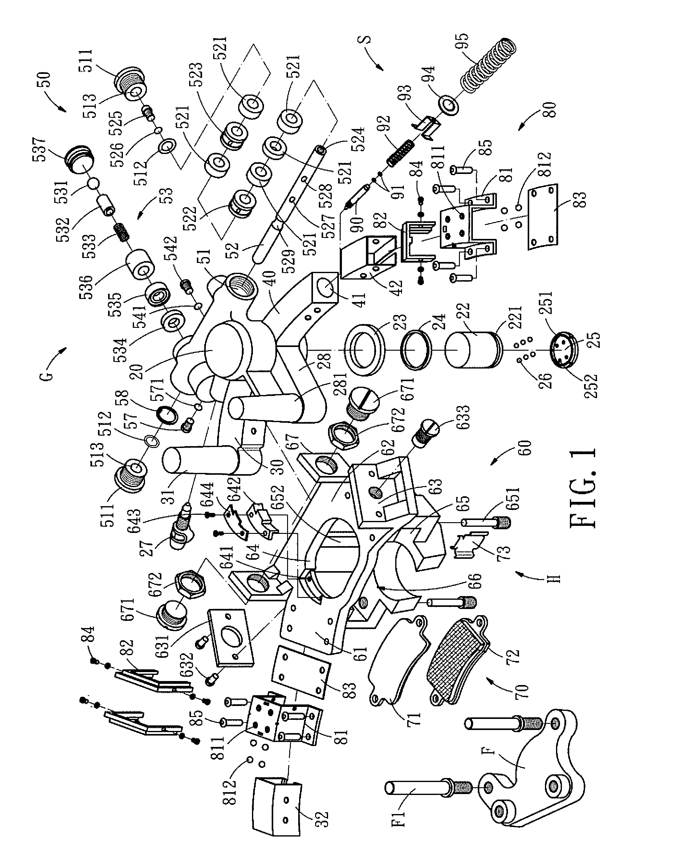
A hydraulic disc brake device comprises: a base assembly mounted on a vehicle, a sliding assembly slideably mounted on the base assembly, a return spring disposed between the base assembly and the sliding assembly, a brake lining assembly, a control valve assembly disposed on the oil pressure system, hydraulic disc brake system that has an antilock effect. The hydraulic disc brake is low cost and has an antilock function.

Description

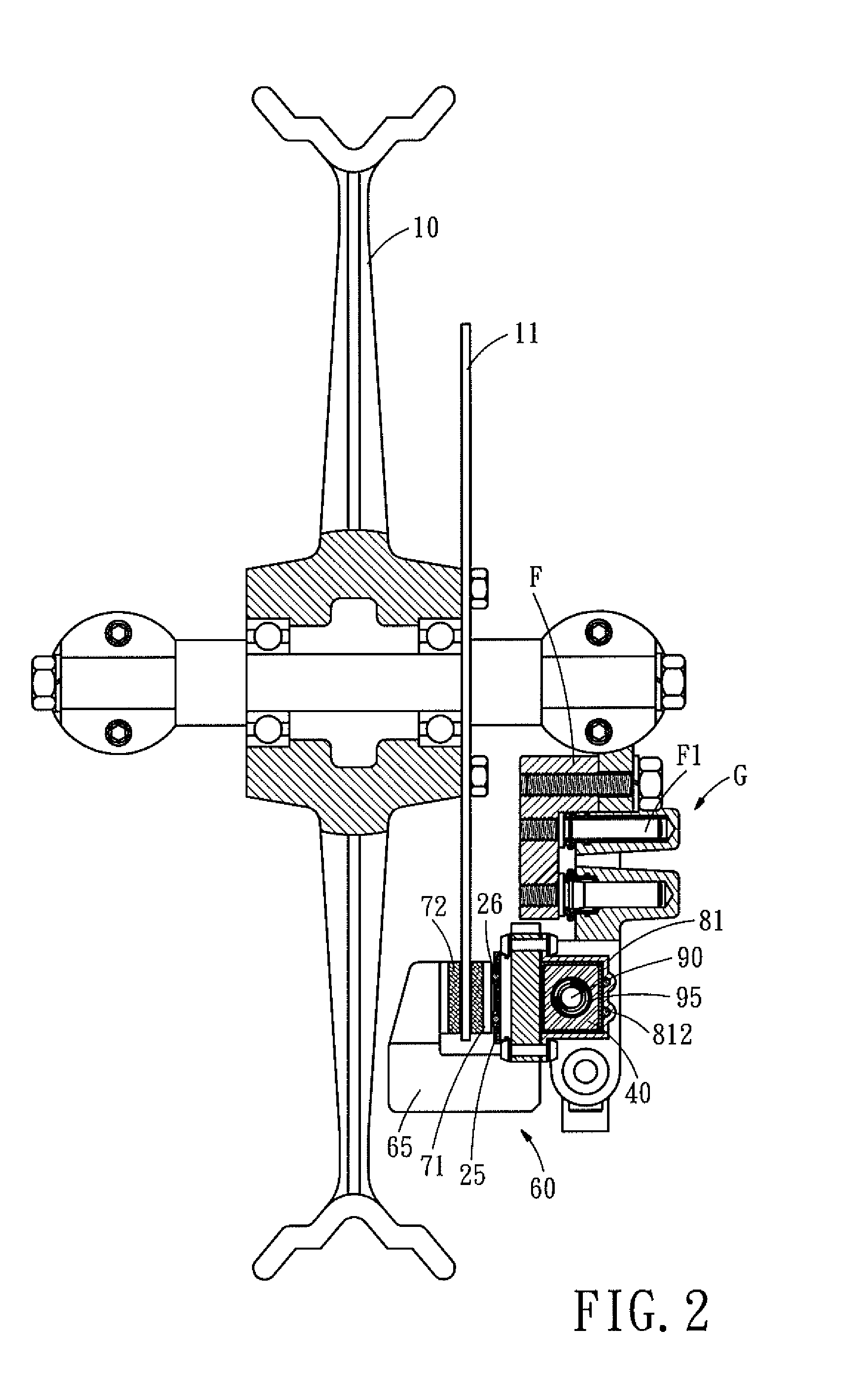
BACKGROUND OF THE INVENTION[0001]1. Field of the Invention[0002]The present invention relates to a hydraulic disc brake device, and more particularly to a hydraulic disc brake device used in a brake system of a vehicle.[0003]2. Description of the Prior Art[0004]Most of the conventional hydraulic disc brake devices utilize the oil cylinder to press the two brake lining shoes against the brake disc from both sides, and the friction force generated between the brake lining shoe and the brake disc stops the vehicle. However, these conventional hydraulic disc brake devices still have the following disadvantages:[0005]The clamping force caused by the oil pressure in the case of an emergency brake is always very great, and the resultant braking force will be excessively large, and thus probably causing a sudden dead lock. As a result, not only will the tire be locked, but also the vehicle will suffer an instant run-out, leading to a skidding or overturning of the vehicle.[0006]The present ...

Claims


Application Information

Patent Timeline
Patent Type & Authority Patents(United States)
IPC IPC(8): F16D55/02B60T1/00B60T1/06B60T8/32B60T8/52B62L1/00F16D65/14
CPCB60T8/3225B60T8/52F16D65/18B62L1/005F16D2121/02F16D2055/0016B60T8/74F16D55/228
Inventor HUANG, TAN-CHENG
Owner HUANG TAN CHENG
Learn More