Electrical connector

a technology of electrical connectors and soldering pads, applied in the direction of incorrect coupling prevention, coupling device connection, coupling device details, etc., can solve the problems of electrical connection failure at the location of soldering pads, and achieve the effect of effective electrical connection

Inactive Publication Date: 2008-09-18
HON HAI PRECISION IND CO LTD
View PDF15 Cites 5 Cited by
  • Summary
  • Abstract
  • Description
  • Claims
  • Application Information

AI Technical Summary

Benefits of technology

[0008]An electrical connector according to an embodiment of the present invention includes an elongated housing formed from an insulative material and defining a lengthwise direction and a transverse direction perpendicular to each other. The housing has a first surface and a second surface, and includes a daughter-card receiving channel on the first surface of the housing and extending along the lengthwise direction, with the daughter-card receiving channel adapted for receiving a mating edge of a daughter-card member. A mother-card receiving channel is defined on the second surface of the housing and extending along the lengthwise direction, with the mother-card receiving channel adapted for receiving a mating edge of a mother-card member. Respective mother-card engagement slots are defined on opposed ends of the housing, each mother-card engagement slot extending from said second surface and along the transverse direction. The mother-card engagement slots are laterally in communication with the mother-card receiving channel. Each mother-card engagement slot is defined by a pair of free extension legs for receiving therein respective lateral edge portions of the mother-card member. A central line of each mother-card engagement slot is aligned with a central line of the mother-card receiving channel in the lengthwise direction of the housing. This configuration of the mother-card engagement slots will allow for the mother-card member to be held coplanar with respect to a middle plane of the mother-card receiving channel where terminals are set to extend thereinto for being in direct contact with soldering pads of the daughter-card member, thereby establishing an effective electrical connection between the electrical connector and the mother-card member.

Problems solved by technology

Thus, there may be some of soldering pads on the mating edge of the card member that are not in direct contact with the terminals of the housing, thereby resulting in electrical connection failure at locations of those soldering pads.
This configuration may also enable the card member to be displaced with respect to a middle plane of the card member receiving channel of the connector, thereby having a same problem described above.

Method used


Image

  • Electrical connector
  • Electrical connector
  • Electrical connector

Examples


Embodiment Construction

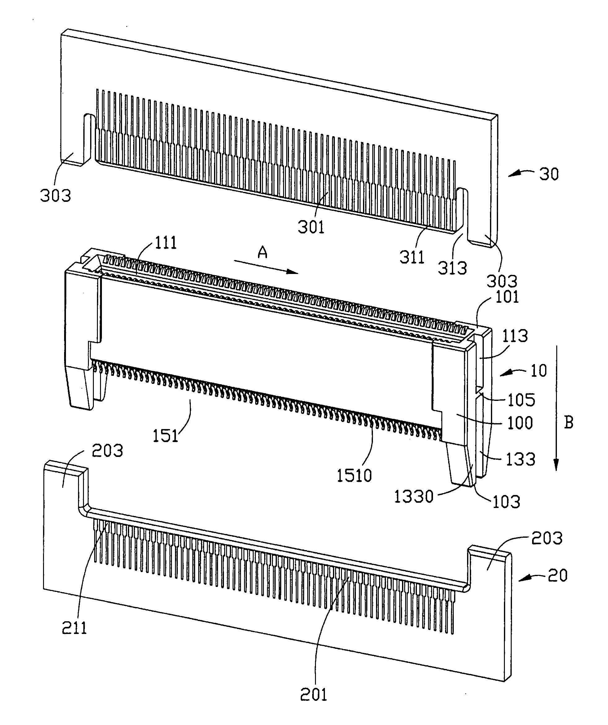
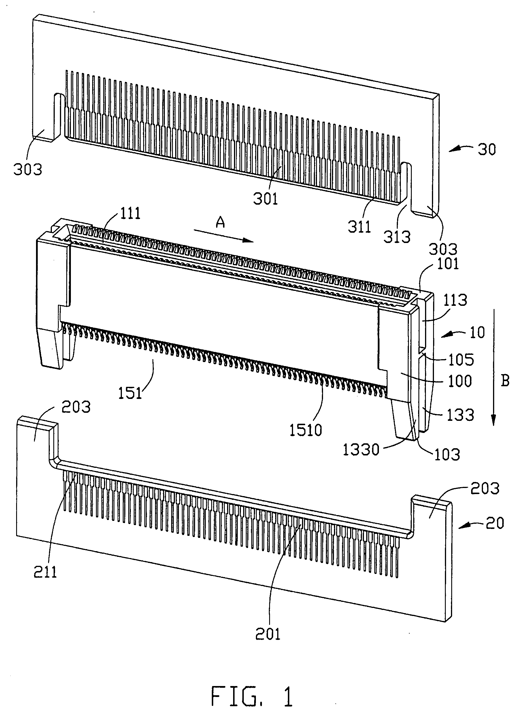
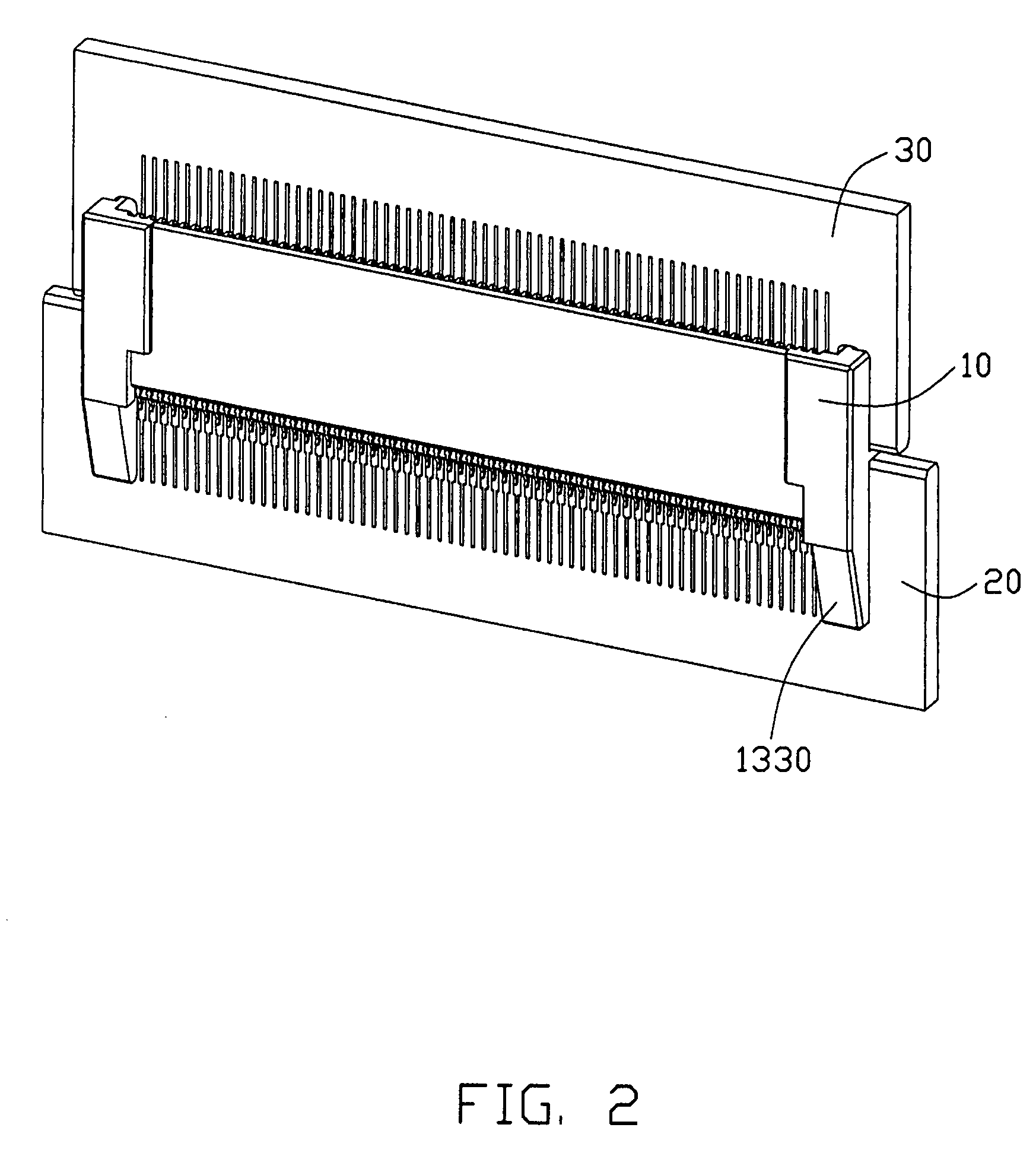
[0016]Referring to FIGS. 1 to 5, an electrical connector 10 for electrically connecting with two circuit boards, generally a parallel arrangement of a mother-card member 20 and a daughter-card member 30, is shown according to a preferred embodiment of the present invention. In this embodiment, the mother-card member 20 defines a mating edge 201 where a plurality of soldering pads 211 is disposed thereon, and two lateral edge portions 203 extending outwardly with a predetermined distance from the mating edge 201 of the mother-card member 20. In other words, the mating edge 201 is recessed with respect to the lateral edge portions 203 of the mother-card member 20. The daughter-card member 30 defines a mating edge 301 where a plurality of soldering pads 311 is disposed thereon, and two lateral edge portions 303 on opposed ends of the mating edge 301 of the daughter-card member 30. The lateral edge portions 303 are laterally spaced from the mating edge 301 by elongated slots 313 defined...


PUM


Abstract

An electrical connector (10) includes an elongated housing (100) having a daughter-card receiving channel (111) on a first surface (101) thereof and extending along a lengthwise direction for receiving a daughter-card member (30). Respective daughter-card engagement slots (113) are defined on opposed ends of the housing, each slot extending from the first surface and along a transverse direction. The slots are laterally separated from the receiving channel for receiving lateral edge portions of the daughter-card member. A central line of each slot is aligned with a central line of the receiving channel in the lengthwise direction such that configuration of the slots will allow for the daughter-card member to be held coplanar with respect to a middle plane of the channel, thereby establishing an effective electrical connection between the connector and the daughter-card member.

Description

BACKGROUND OF THE INVENTION[0001]1. Field of the Invention[0002]The present invention relates to the art of electrical connectors, and more particularly to an electrical connector for electrically connecting together circuit boards, such as a mother-card member and a daughter-card member.[0003]2. Description of the Related Art[0004]Chinese Pat. No. 2845210 issued to Cai Zhou-Xuan on Dec. 6, 2006 discloses a related conventional electrical connector normally named as “a card-edge connector”. The card edge connector includes an insulative elongated housing defining a card member receiving channel extending from a surface of the housing and along a lengthwise direction. A plurality of terminals is arranged in series and on the housing along opposed lengthwise edges of the card member receiving channel. The terminals include resilient arms defining opposed contact sections extending into the card member receiving channel for resiliently clipping a mating edge of the card member and for ...

Claims


Application Information

Patent Timeline
Patent Type & Authority Applications(United States)
IPC IPC(8): H01R9/00H01R12/71
CPCH01R12/721H01R31/06
Inventor SABO, JAMES M.
Owner HON HAI PRECISION IND CO LTD
Why Eureka
Try Eureka