AI technical title is built by PatSnap AI team. It summarizes the technical point description of the patent document.
a technology of active discharge and pulse generator, which is applied in the field of pulse generation, can solve the problems of skewing pulses, limiting the frequency at which pulses can be delivered, and dissipating twice the power, and achieve the effect of reducing the power dissipation during active discharg
Active Publication Date: 2008-09-18
ADVANCED NEUROMODULATION SYST INC
View PDF8 Cites 14 Cited by
Summary
Abstract
Description
Claims
Application Information
AI Technical Summary
This helps you quickly interpret patents by identifying the three key elements:
Problems solved by technology
Method used
Benefits of technology
Benefits of technology
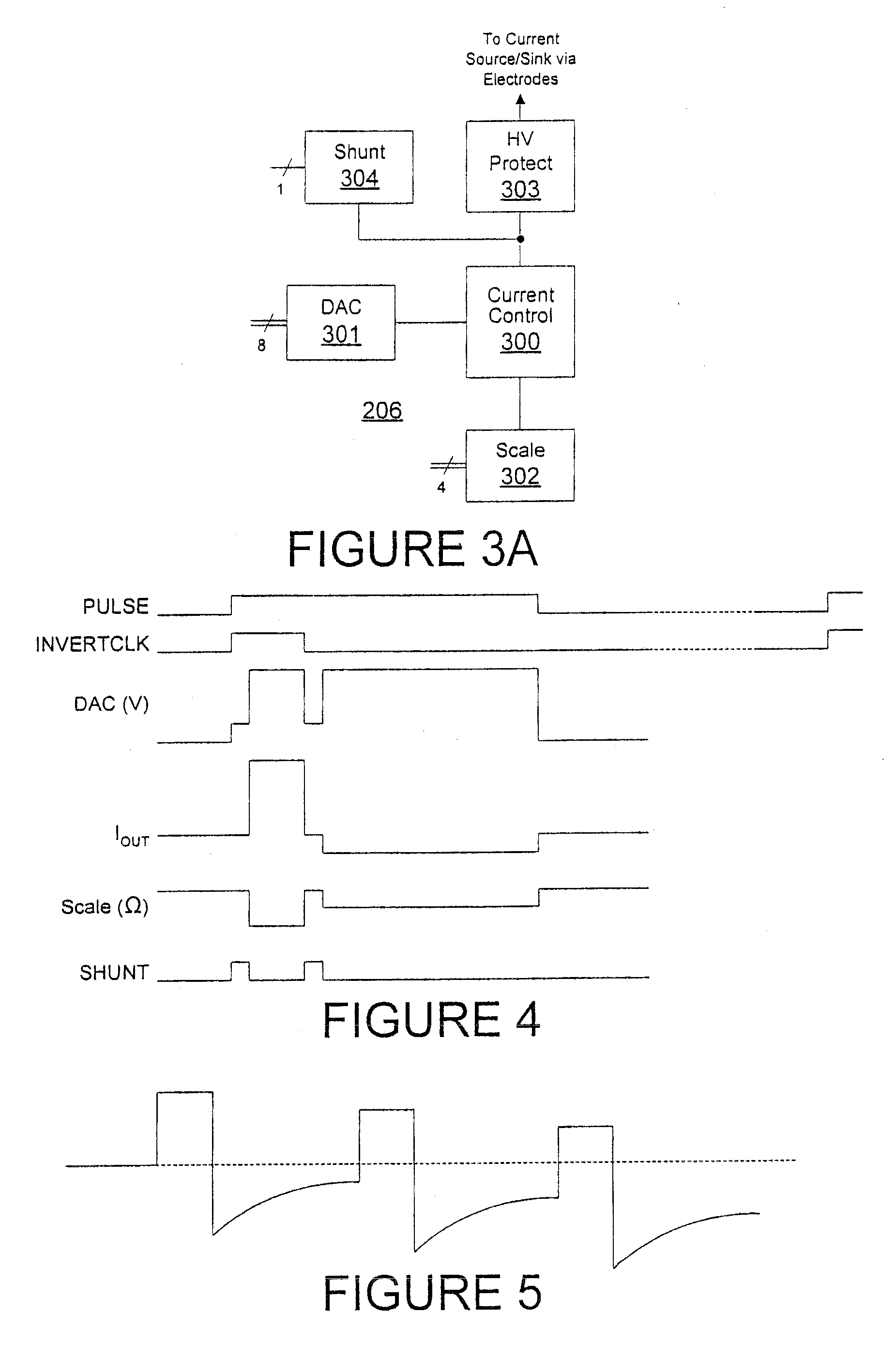
[0005]To address the above-discussed deficiencies of the prior art, it is a primary object of an embodiment of the present invention to provide, for use in an implantable pulse generator, active discharge pulses following stimulation pulses and having opposite polarity of the stimulation pulses as well as programmable amplitude and duration. Approximately the same total net current flow is delivered during active discharge pulses as during the stimulation pulses, but in the opposite direction and optionally at a lower amplitude. By reducing the driving voltage and a variable load within the electrical path for delivery of the pulses, power dissipation during active discharge is reduced.
Problems solved by technology
In delivering constant current electrical stimulation pulses by an implantable pulse generator to electrodes implanted near a stimulation site, capacitive connections of the electrodes to a pulse generator circuit output driver can accumulate charge if balanced pulses are not employed, resulting in skewing the pulses over time.
Simply using balanced pulses, however, dissipates twice the power.
Simple passive discharge, on the other hand, requires time to dissipate accumulated charge, potentially limiting the frequency at which pulses can be delivered.
In addition, significant charge may remain accumulated between pulses, skewing the pulses over time.
Method used
Image
Click on the blue label to locate the original text in one second.
Reading with bidirectional positioning of images and text.
Examples
Embodiment Construction
[0016]FIGS. 1 through 7, discussed below, and the various embodiments used to describe the principles of the present invention in this patent document are by way of illustration only and should not be construed in any way to limit the scope of the invention. Those skilled in the art will understand that the principles of the present invention may be implemented in any suitably arranged device.
[0017]Before undertaking the detailed description below, it may be advantageous to set forth definitions of certain words or phrases used throughout this patent document: the terms “include” and “comprise,” as well as derivatives thereof, mean inclusion without limitation; the term “or” is inclusive, meaning and / or; the phrases “associated with” and “associated therewith,” as well as derivatives thereof, may mean to include, be included within, interconnect with, contain, be contained within, connect to or with, couple to or with, be communicable with, cooperate with, interleave, juxtapose, be ...
PUM
Abstract
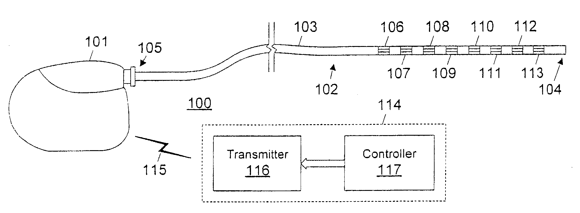
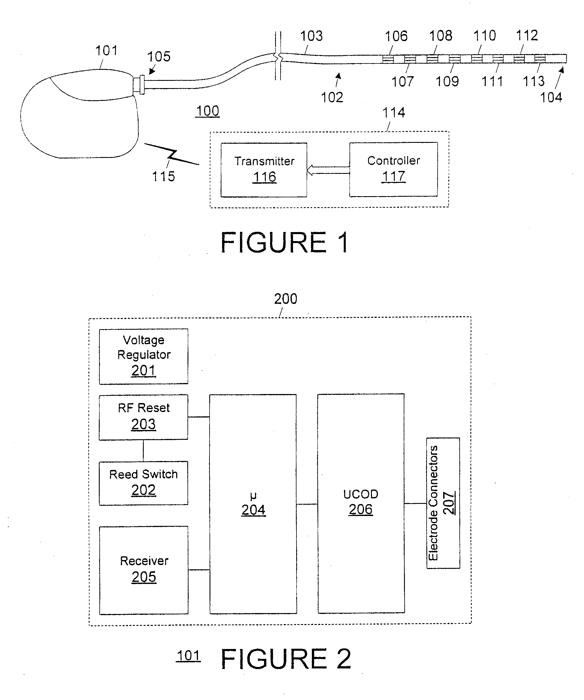
To avoid charge accumulation on capacitive connections to implanted electrodes during delivery of stimulation pulses, stimulation pulses are followed by active discharge pulses having opposite polarity of the stimulation pulses. The active discharge pulses preferably have at least one pulse attribute magnitude (e.g., duration, voltage, and / or current) different than a corresponding stimulation pulse and are preferably programmable. Approximately the same total net current flow is delivered during active discharge pulses as during the stimulation pulses, but in the opposite direction and optionally at a lower amplitude. In addition, by reducing the driving voltage and a variable load within the electrical path for delivery of the pulses, power dissipation during active discharge is preferably reduced.
Description
CROSS-REFERENCE TO RELATED APPLICATIONS[0001]This application is a continuation of U.S. application Ser. No. 11 / 105,188, filed Apr. 12, 2005, pending, which claims the benefit of U.S. Provisional Application No. 60 / 561,437, filed Apr. 12, 2004, and related to commonly assigned U.S. application Ser. No. 11 / 105,191, filed Apr. 12, 2005, pending, U.S. application Ser. No. 11 / 105,186, filed Apr. 12, 2005, pending, U.S. application Ser. No. 11 / 105,332, filed Apr. 12, 2005, now U.S. Pat. No. 7,180,760, U.S. application Ser. No. 11 / 105,190, filed Apr. 12, 2005, pending, and U.S. Provisional Application No. 60 / 648,556, filed Jan. 31, 2005, the disclosures of which are incorporated herein by reference.TECHNICAL FIELD[0002]The present invention is directed, in general, to pulse generation and, more specifically, to active discharge of a pulse generator.BACKGROUND OF THE INVENTION[0003]In delivering constant current electrical stimulation pulses by an implantable pulse generator to electrodes ...
Claims
Application Information
Patent Timeline
Application Date:The date an application was filed.
Publication Date:The date a patent or application was officially published.
First Publication Date:The earliest publication date of a patent with the same application number.
Issue Date:Publication date of the patent grant document.
PCT Entry Date:The Entry date of PCT National Phase.
Estimated Expiry Date:The statutory expiry date of a patent right according to the Patent Law, and it is the longest term of protection that the patent right can achieve without the termination of the patent right due to other reasons(Term extension factor has been taken into account ).
Invalid Date:Actual expiry date is based on effective date or publication date of legal transaction data of invalid patent.
Patent Type & AuthorityApplications(United States)
IPC IPC(8): A61N1/08A61N1/14A61N1/36
CPCA61N1/14A61N1/3782A61N1/36146A61N1/36125
InventorVARRICHIO, ANTHONY J.TRANCHINA, BENJAMIN A.

