[0013]It is a further object that the electric storage device incorporated within the thermal glove be adapted for fast, safe, and repeatable recharging suitable for long-term use.
[0016]In today's society, health and comfort reign supreme, and the Waltco
Warm Hands Glove referred to herein below as a thermal glove provides both elements. The thermal glove of the present invention provides hand warmth for
outdoor workers, such as construction workers, city workers, groundskeepers, telephone and utilities workers, air traffic controllers, parcel workers, couriers, truckers, soldiers / military personnel—whose duties often keep them outside—summer and winter. Cyclists, warehouse and industrial workers—whose jobs subjects them to ice sleet,
snow and freezing temperatures that can affect circulation and cause
frostbite also can benefit from Waltco
Warm Hands Gloves. These gloves also provide hand warmth to everyday commuters that travel to and fro, whose hands are sensitive to cold temperatures in the civilian communities. There are also
health benefits to these gloves which can provide
heat therapy for individuals who have been stricken with
arthritis, carpel tunnel syndrome,
joint disease in the hands, swelling in the hands, sprains, strains, or individuals who have had various types of orthopedic
surgical procedures on their hands and other ailments that affect the hands and often require heat applications for
heat therapy. The gloves can also be used by
athletes for
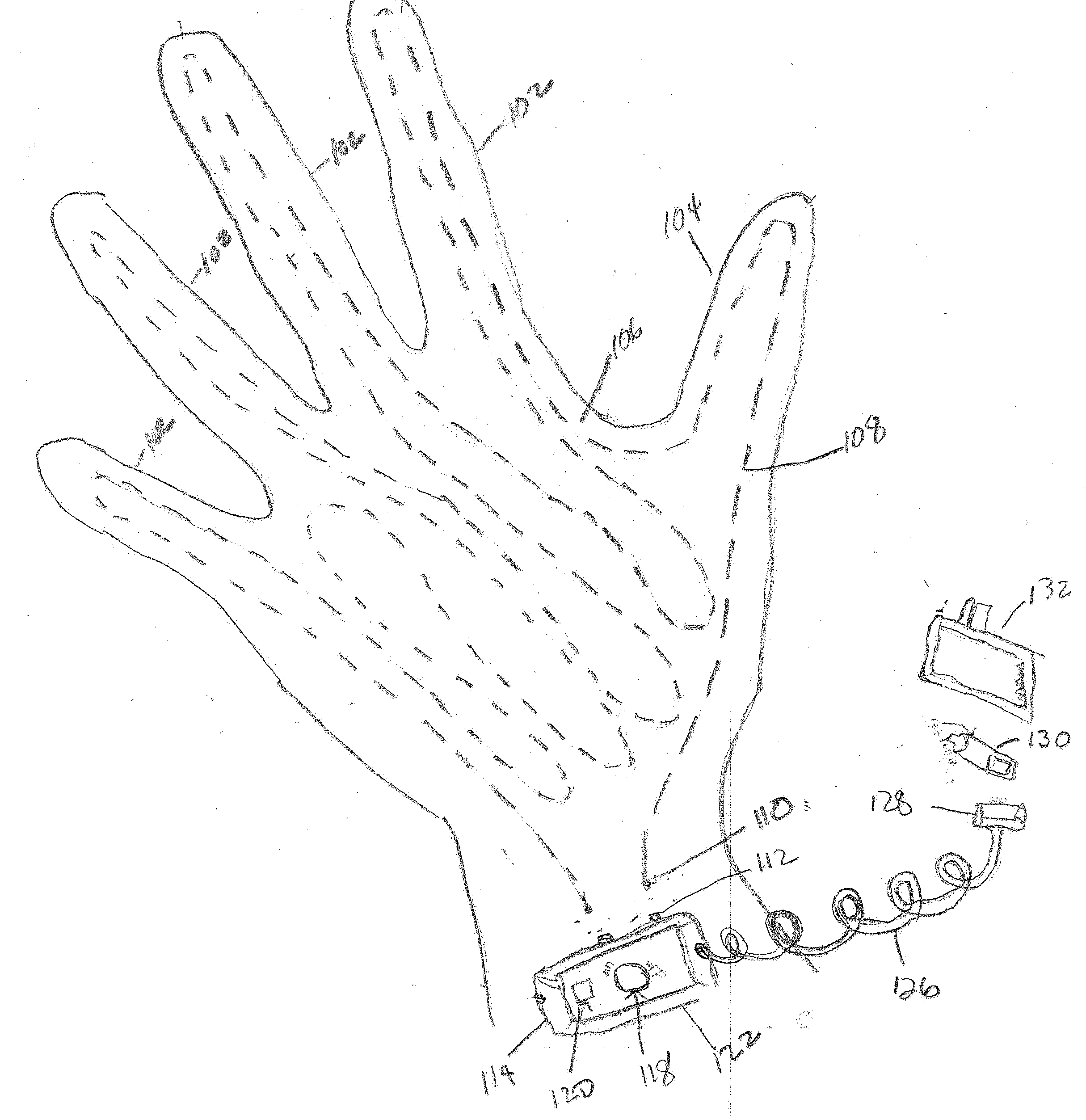
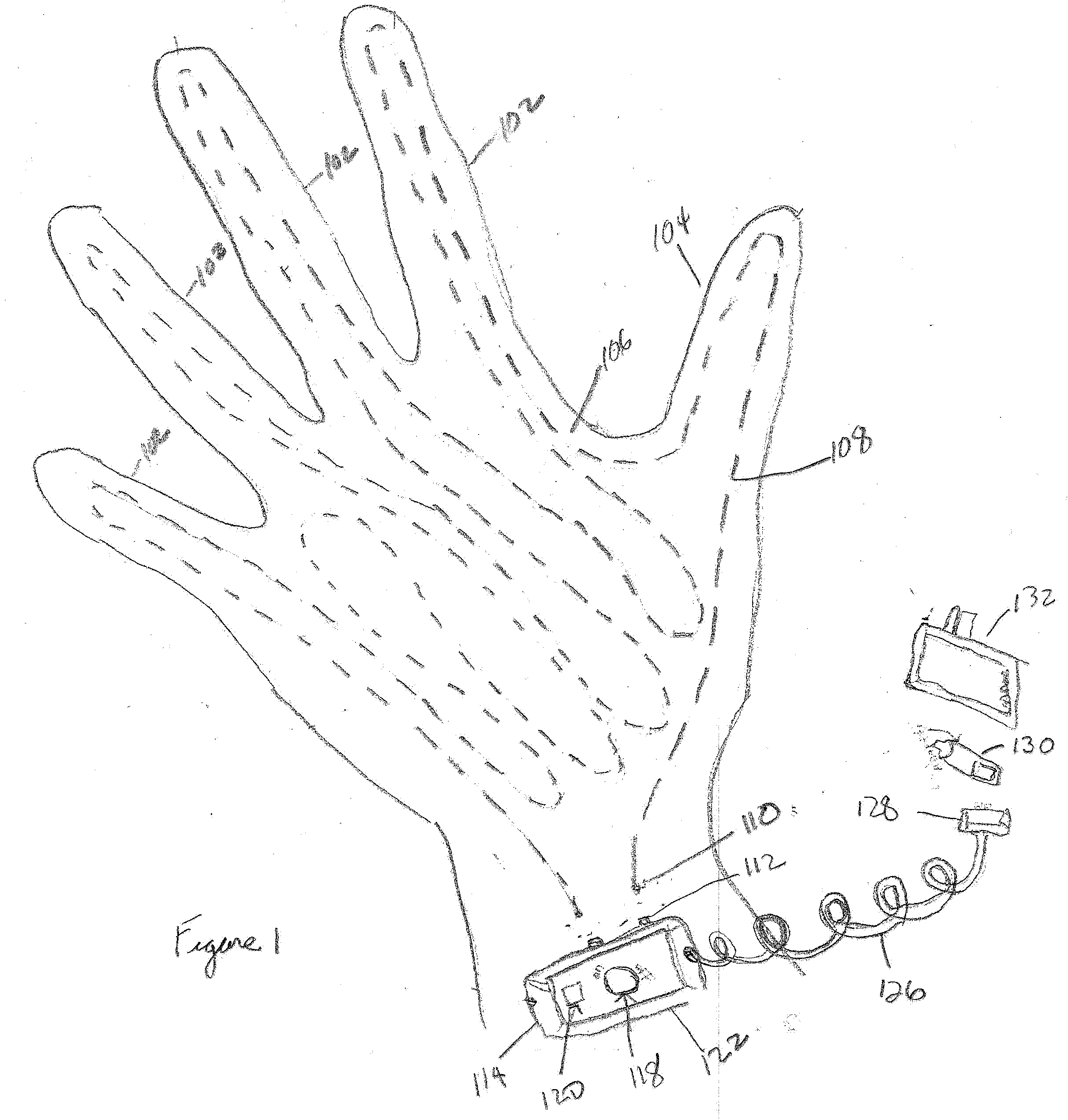
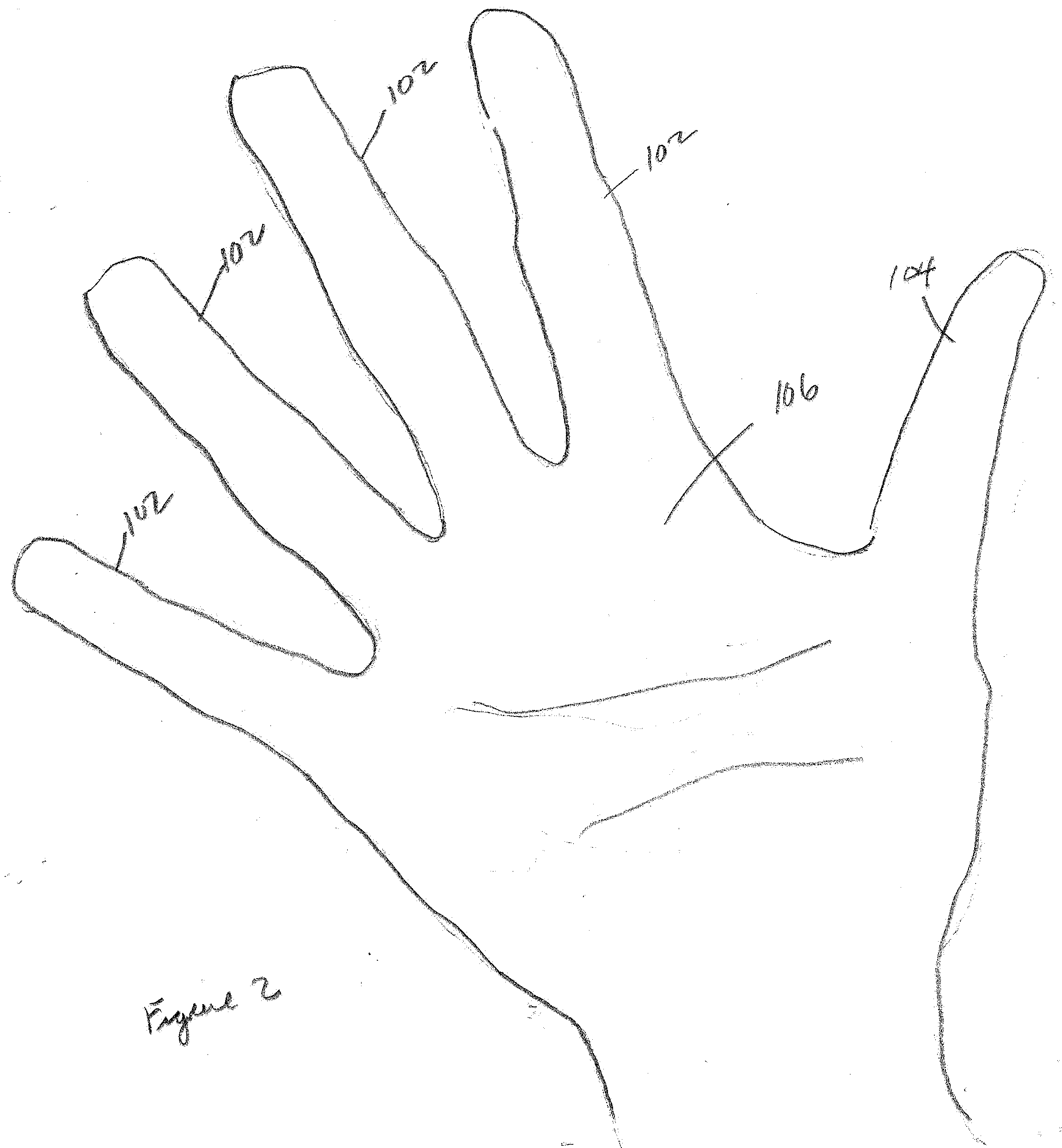
heat therapy to their hands which is a very valuable asset to their careers. The Waltco Warm Hand Gloves can come in various styles, sizes, materials, textures, colors, thicknesses, lengths, and cosmetic designs. These gloves are designed with heating elements within the inner lining of the gloves' top, sides, palms, and / or
wrist section and an outer lining of heat deflecting material within the glove. These gloves have a temperature control device, which can be housed within the gloves or separate from the gloves, either analog or digital, which control the temperature of the gloves. The temperature control device can be battery powered and / or rechargeable via wall socket (AC / DC), car cigarette lighter, or an external battery charging device, which can make recharging the glove convenient for the
end user, whether they are at home or traveling abroad. The outer glove can be constructed of leather, nylon, rayon
polyester, or any other man made and or
natural material. The
wrist section of the gloves can have elastic type bands to assist in keeping the heat from escaping. The gloves can benefit people from all walks of life and all areas of professions—athletically, medically, everyday wear, or those who are
expose to the outdoor elements, during their on the job assignments, such as soldiers.

