Air Conditioner for Vehicle

a technology for air conditioners and vehicles, applied in vehicle heating/cooling devices, refrigerating machines, sorption machines, etc., can solve the problems of limited air blowing into the vehicle interior, difficult control of blower fan, and inability to send out uncomfortable cool air, etc., to achieve the effect of enhancing the rising speed of the interior temperatur

Inactive Publication Date: 2008-09-25
CALSONIC KANSEI CORP
View PDF6 Cites 18 Cited by
  • Summary
  • Abstract
  • Description
  • Claims
  • Application Information

AI Technical Summary

Benefits of technology

[0021]According to this configuration, even when the refrigerant temperature or the cooling water temperature is low, a small quantity of air is sent so that a driver or the like does not feel uncomfortable. Therefore, uncomfortable cool air is not sent out as compared with the conventional technique in which air is sent immediately after the air conditioner is actuated. Further, the quantity of air is set to the greatest one of a small quantity of air determined according to the refrigerant temperature, a small quantity of air determined according to the cooling water temperature, and a small quantity of air determined according to the elapsed time after actuation. Therefore, it is possible to further enhance the rising speed of the interior temperature.
[0022]According to the above configuration, when the refrigerant temperature is low, it is possible to appropriately control the air conditioner wind so that the driver or the like does not feel uncomfortable.

Problems solved by technology

However, in a vehicle such as an electric car or the like that does not have a heat source which uses the engine cooling water, since air conditioner wind is heated by heat of refrigerant, it is difficult to apply the blower fan control.
According to this configuration, when the refrigerant temperature is low, the blow of air into the vehicle interior is limited.
Thus, uncomfortable cool air is not sent out as compared with the conventional technique in which air is sent immediately after the air conditioner is actuated.

Method used


Image

  • Air Conditioner for Vehicle
  • Air Conditioner for Vehicle
  • Air Conditioner for Vehicle

Examples


first embodiment

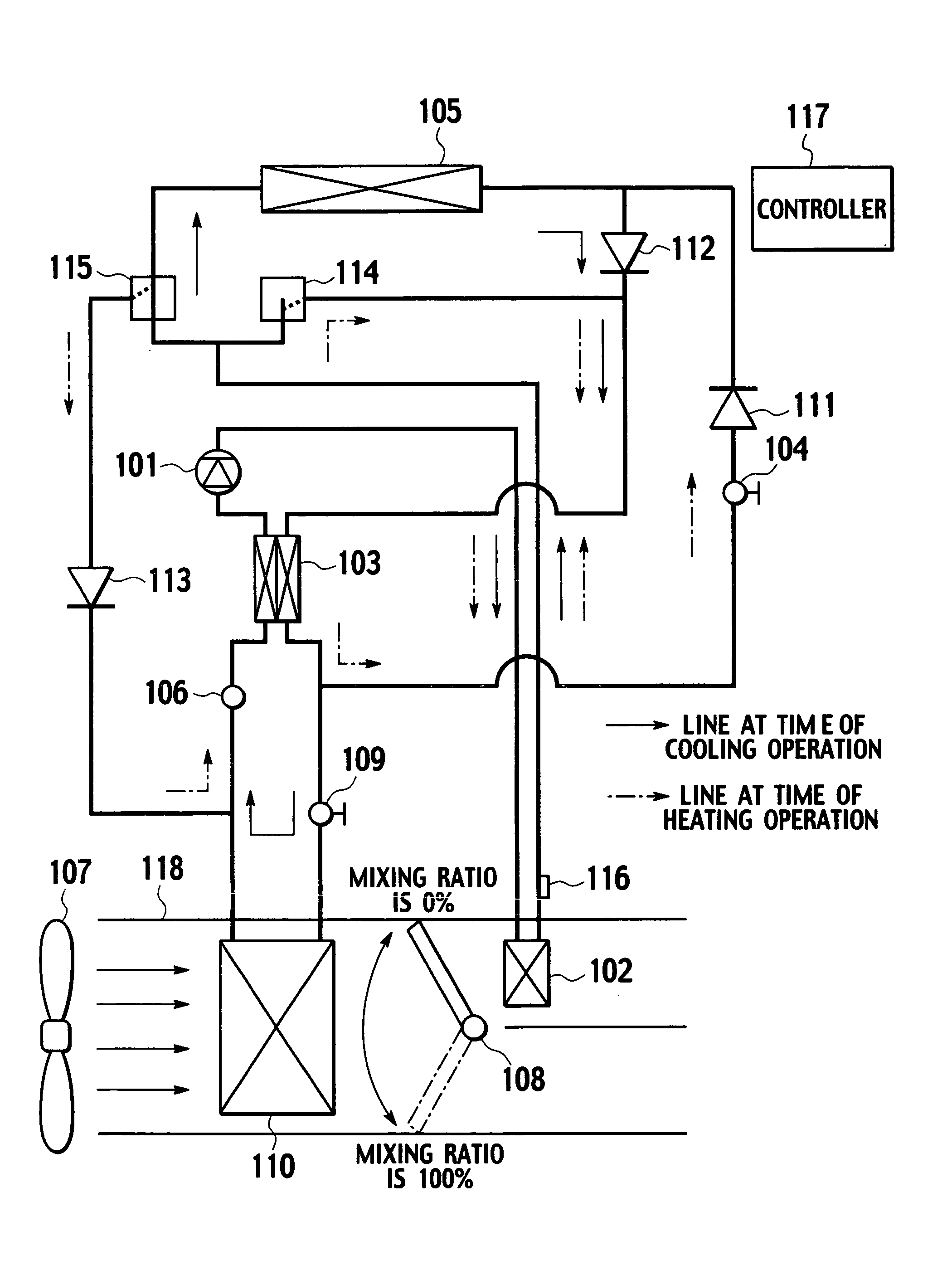
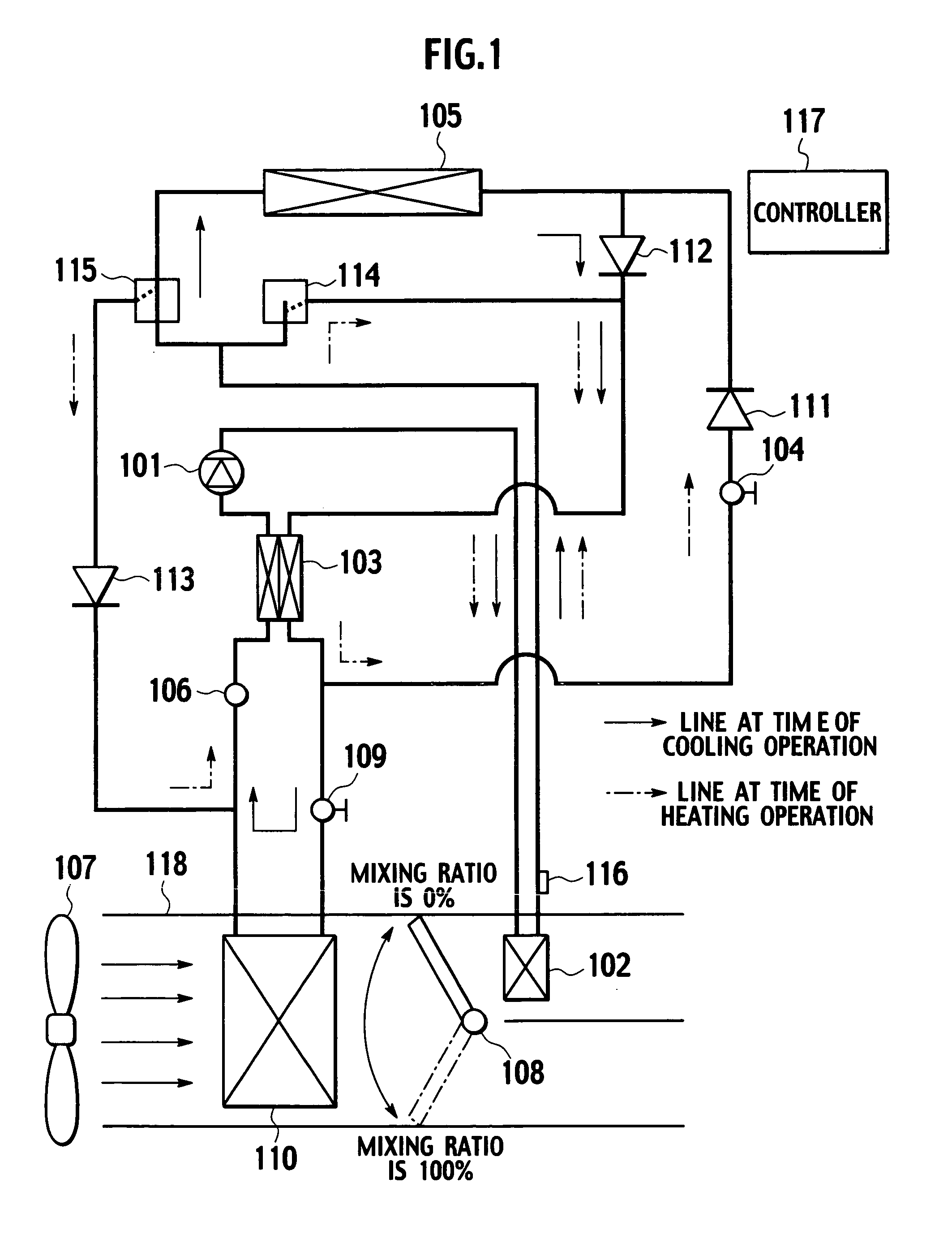
[0038]FIG. 1 is a schematic configuration diagram of an air conditioner for a vehicle according to a first embodiment.

[0039]An air conditioner for a vehicle which is applied to an electric car or the like, in which refrigerant is used as a heat source will be explained. The air conditioner for a vehicle of the embodiment includes a heating cycle (shown with -•-→in the drawing) which circulates carbon dioxide as the refrigerant to exchange heat between the refrigerant and air.

[0040]The heating cycle includes a compressor 101, a sub-heat exchanger 102 (internal heat exchanger 103), an expansion valve 104, an exterior heat exchanger 105, and an accumulator 106 that are communication-connected with one another through pipes in this order, and refrigerant compressed by the compressor 101 is circulated through these members.

[0041]The compressor 101 obtains a driving force from a motor (not shown) and compresses gas-phase carbon dioxide, and discharges the compressed carbon dioxide as high...

second embodiment

[0073]FIG. 8 is a schematic configuration diagram of an air conditioner for a vehicle according to a second embodiment. Like reference signs denote like parts as those shown in FIG. 1, and bold lines shows paths of the heating cycle, and broken lines show paths of the cooling cycle (explanation thereof is omitted).

[0074]The air conditioner for a vehicle of this embodiment is applied to an engine vehicle. Engine cooling water, carbon dioxide, and refrigerant are used as heat sources. The configuration of this embodiment can be applied to R134a refrigerant. In this case, the internal heat exchanger 103 is not a fundamental element.

[0075]According to the air conditioner for a vehicle of this embodiment, a heater core 119 is disposed in the air conditioner duct 118, and engine cooling water flowing through a cooling passage of an engine 120 is circulated through a pipe. The heater core 119 heats the air conditioner wind sent out from the blower fan 107 by the engine cooling water. A wat...


PUM


Abstract

A controller (117) for an air conditioner using a refrigerant as a heat source is constructed such that, when a refrigerant temperature detected by a refrigerant temperature sensor (116) has reached a specified value, air with a volume of normal setting is blown into a vehicle compartment, and when the refrigerant temperature has not reached the specified value, air blowing into the vehicle compartment by a blower fan (107) is limited.

Description

TECHNICAL FIELD[0001]The present invention relates to an air conditioner for a vehicle, and more particularly, to an air conditioner for a vehicle suitable for electric cars and fuel cell cars (hereinafter, “electric car or the like”).BACKGROUND ART[0002]Conventional air conditioners for a vehicle, using engine cooling water as a heat source have a problem that the engine cooling water is not sufficiently heated immediately after an engine is started and thus, uncomfortable cool air is adversely sent from a vent until the temperature of the cooling water reaches a predetermined temperature, thereby making a driver or a passenger (hereinafter, “driver or the like”) feel uncomfortable.[0003]As a conventional technique for solving this problem, if an engine is started while the temperature of the engine cooling water is low, a small quantity of air is sent into a vehicle interior until predetermined time elapses after starting the engine (Japanese Patent No. 258129).DISCLOSURE OF THE I...

Claims


Application Information

Patent Timeline
Patent Type & Authority Applications(United States)
IPC IPC(8): F25B15/00B60H1/00B60H1/08
CPCB60H1/00392B60H1/00899B60H1/00828
Inventor NAKAMURA, KOJIROIGHUCHI, MASAHIRO
Owner CALSONIC KANSEI CORP
Why Eureka
Try Eureka