Voltage regulating apparatus and method and voltage regulator thereof

a voltage regulator and voltage regulation technology, applied in the direction of electric variable regulation, process and machine control, instruments, etc., can solve the problems of excessive current or power surge of output voltage when the device is used, the time required to stabilize the current is too long, and the rise speed of output voltage is slow

Inactive Publication Date: 2009-05-28
REALTEK SEMICON CORP
View PDF15 Cites 7 Cited by
  • Summary
  • Abstract
  • Description
  • Claims
  • Application Information

AI Technical Summary

Benefits of technology

[0008]A first objective of the present invention is to provide a voltage regulating apparatus and method thereof capable of ensuring sufficient dead time to prevent from the short-circuit current.
[0009]A second objective of the present invention is to provide a voltage regulating apparatus and method thereof capable of enhancing the rising speed of the output voltage to prevent from the time required to stabilize the current being too long.
[0010]A third objective of the present invention is to provide a voltage regulating apparatus and method thereof capable of having a high voltage conversion efficiency.
[0012]A fifth objective of the present invention is to provide a voltage regulating apparatus and method thereof capable of reducing the power consumption.
[0013]To achieve the foregoing objectives, according to an aspect of the present invention. Accordingly, the present invention is directed to a voltage regulating apparatus and method thereof. The apparatus, method or voltage regulator is capable of shortening the time required to stabilize the output voltage and effectively solving the above problems.

Problems solved by technology

However, as a large inductor A10 is required at the output terminal of the regulator's architecture, an excessively high current or power surge of the output voltage may occur when the device is on.
However, use of this apparatus results in the rising speed of the output voltage being slow, and the time required to stabilize the current is too long.
What's worse, during the early stages of the switch regulator being turned on, the duty cycle controlling the activation of an N / P MOS A40 (i.e., NMOS / PMOS) is quite low due to the extremely low output voltage, such that the N / P MOS A40 may be simultaneously turned on due to a false control signal, thus generating a short-circuit current.
However, an additional circuit must be employed at the cost of extra current using this method.
Due to the strict requirements of chips (ICs) of the current specification when in sleep mode (power saving mode) and the complex design and high current demands of the switch regulator when inactive, it is difficult to achieve the current specification required, when the regulator is in sleep mode.
Furthermore, the application will become more complicated if an additional auxiliary circuit is also needed.

Method used


Image

  • Voltage regulating apparatus and method and voltage regulator thereof
  • Voltage regulating apparatus and method and voltage regulator thereof
  • Voltage regulating apparatus and method and voltage regulator thereof

Examples


Embodiment Construction

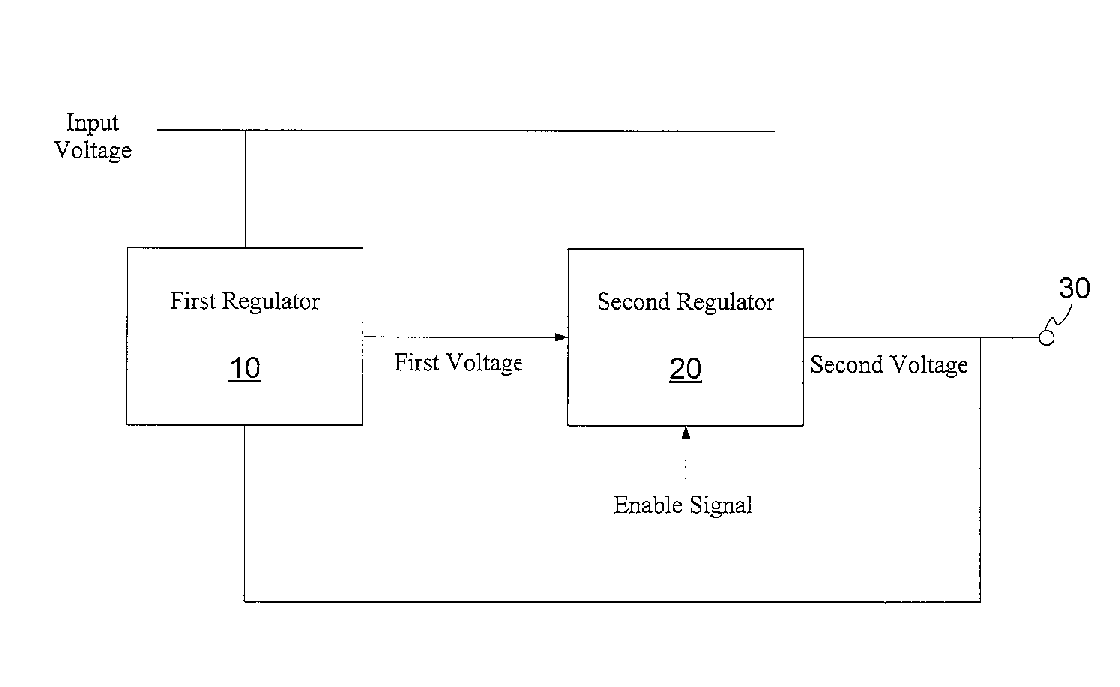
[0023]Types of regulator apparatuses are described first before the explanation of the present invention. A regulator apparatus functions to convert an input voltage, and to output a steady operating voltage which is used by other circuits. Regulator apparatuses can be classified into boost regulators and buck regulators depending on the comparison between the input voltage and the output voltage.

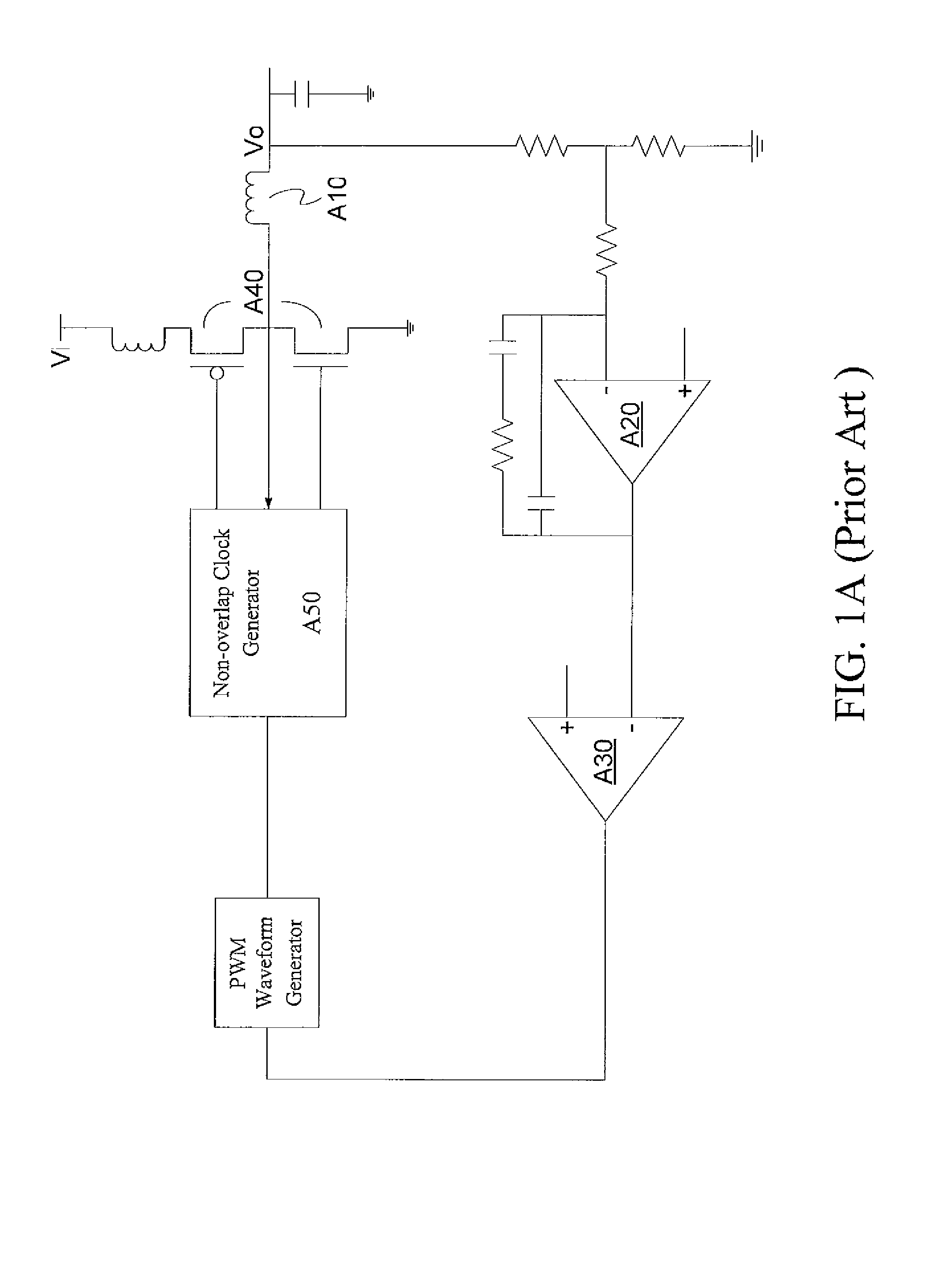
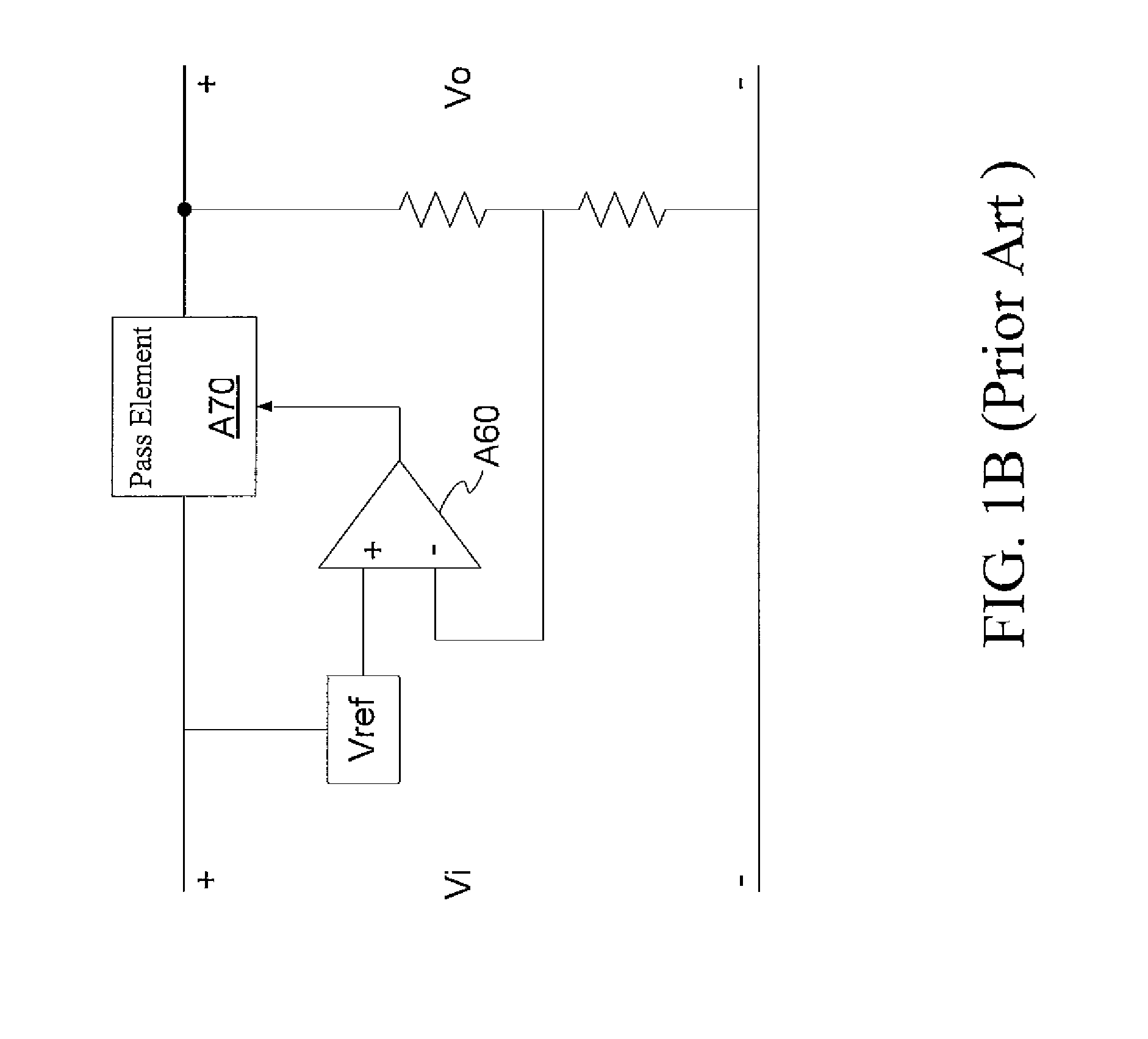
[0024]Moreover, regulators may also be divided into switch regulators and linear regulators depending on the architecture and applications thereof. FIG. 1A shows the architecture of a switch regulator, and FIG. 1B shows the architecture of a linear regulator. Referring to FIG. 1B, the linear regulator includes a comparator A60 and a pass element A70. The pass element A70 may be constituted of a variety of different elements so as to form various types of linear regulators.

[0025]Being simpler in structure than a switch regulator, a linear regulator is superior to the switch regulator in circ...


PUM


Abstract

A voltage regulating apparatus and method and voltage regulator thereof are presented. The apparatus includes a first regulator and a second regulator. The first regulator is used for receiving an input voltage and outputting a first voltage according to the input voltage. When the input voltage reaches a steady voltage value, the second regulator is turned on so as to receive the first voltage provided by the first regulator and output a second voltage according to the first voltage or the input voltage.

Description

CROSS-REFERENCES TO RELATED APPLICATIONS[0001]This non-provisional application claims priority under 35 U.S.C. §119(a) on Patent Application No(s). 96145263 filed in Taiwan, R.O.C. on 2007111 / 28, the entire contents of which are hereby incorporated by reference.BACKGROUND OF THE INVENTION[0002]1. Field of Invention[0003]The present invention relates to a voltage regulating apparatus and method, and more particularly to a voltage regulating apparatus and method and voltage regulator thereof.[0004]2. Related Art[0005]Please refer to FIG. 1A, in which the architecture of a switch regulator in the prior art is shown. The conventional switch regulator has a high voltage conversion efficiency, and is thus commonly used to convert a large voltage difference and a large load current. However, as a large inductor A10 is required at the output terminal of the regulator's architecture, an excessively high current or power surge of the output voltage may occur when the device is on. Therefore, ...

Claims


Application Information

Patent Timeline
Patent Type & Authority Applications(United States)
IPC IPC(8): G05F1/00
CPCG05F1/563G05F1/56
Inventor CHEN, YI-HUEILEE, CHAO-CHENG
Owner REALTEK SEMICON CORP
Why Eureka
Try Eureka