Power output control circuit and multi-layer power supply system

A power supply output and control circuit technology, applied in control/regulation systems, output power conversion devices, DC power input conversion to DC power output, etc., can solve problems such as long start-up time, unclear start-up sequence, and large start-up current , to achieve the effect of improving the starting ability, clear and reliable starting sequence, and stabilizing the output voltage

Active Publication Date: 2014-02-05
MORNSUN GUANGZHOU SCI & TECH
View PDF5 Cites 7 Cited by
  • Summary
  • Abstract
  • Description
  • Claims
  • Application Information

AI Technical Summary

Problems solved by technology

[0013] Another technical problem to be solved by the present invention is to provide a multi-layer power supply system using the above-mentioned power output control circu

Method used


Image

  • Power output control circuit and multi-layer power supply system
  • Power output control circuit and multi-layer power supply system
  • Power output control circuit and multi-layer power supply system

Examples


Embodiment 1

[0048] Such as Figure 5 As shown, the power supply output control circuit B of the present invention is arranged between the output terminal of the power supply circuit A and the load, and it is composed of a switch tube and a detection control circuit with a preset voltage value, and the switch tube is connected in series at the output of the power supply circuit A Between the terminal and the load, the detection control circuit detects the output voltage of the power supply circuit A, and controls the switching tube to turn off when the output voltage is lower than the preset voltage value, and controls the switching tube to turn off when the output voltage is above the preset voltage value conduction. Wherein, the load may be a current load or a resistance load, and a large capacitance may be connected in parallel.

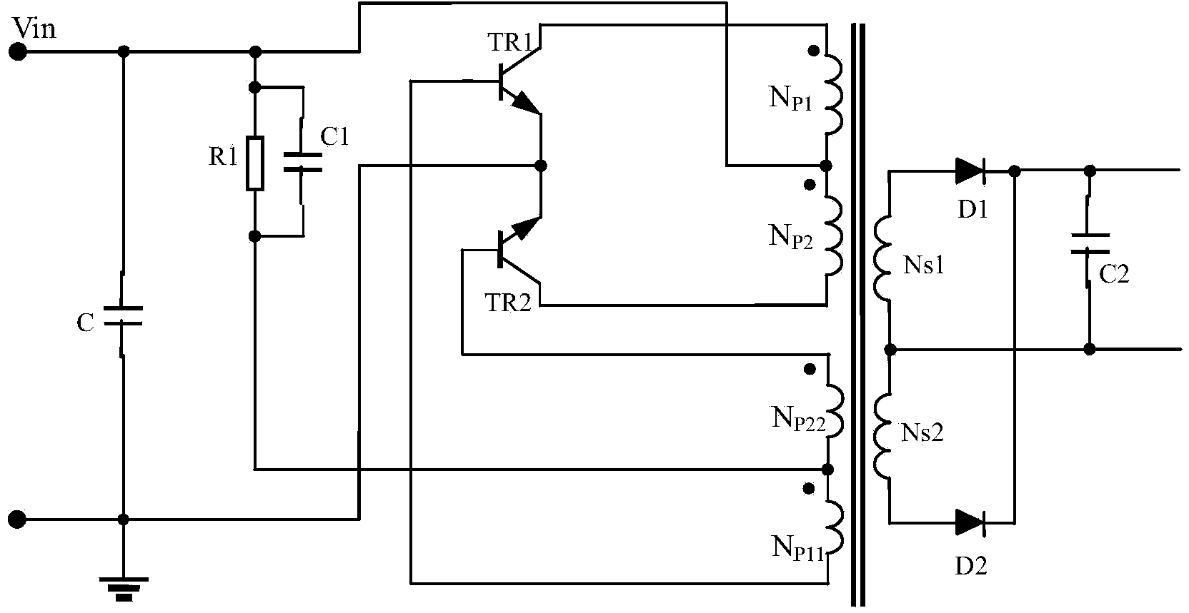
[0049] Figure 7 The power supply output control circuit B of Embodiment 1 of the present invention is shown, the switch tube is a PNP transistor Q1, the de...

no. 1 example approach

[0055]When adopting the existing scheme, the power supply circuit is directly connected to the load circuit, and the power supply output control circuit is not connected in the middle. Since the voltage cannot rise rapidly when the output load has capacitance, in order to show the difference in start-up sequence between the first embodiment of the present invention and the existing solution, a common DC power supply with a start-up time of about 8 mS is used here to supply power to the power circuit. The start-up waveform of the existing power control scheme is as follows Figure 8 shown. The start-up waveform when using the power control scheme of the first embodiment of the present invention is as follows Figure 9 shown. Waveform 1 in the figure is the power supply voltage variation waveform, and waveform 2 is the load voltage variation waveform. It can be seen from the start-up waveform diagram that in the existing scheme, as the output voltage of the power supply is es...

no. 1 example

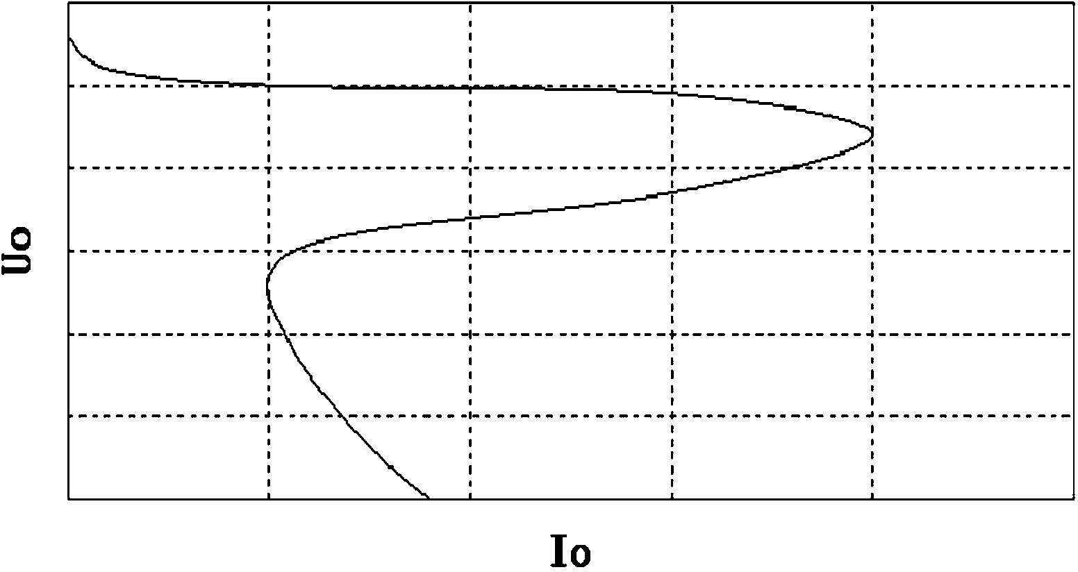
[0057] In order to illustrate the starting capability of the power supply under the scheme of the first embodiment of the present invention, the input voltage of the power supply is stepped up, and the output voltage waveform of the power supply is tested to illustrate the difference between the first embodiment of the present invention and the existing scheme. The test waveform of the existing scheme is as follows Figure 10 , the test waveform of the first embodiment of the present invention is as follows Figure 11 . Waveform 1 in the figure is the waveform of the voltage change of the power supply, and waveform 2 is the waveform of the load voltage change of the measured power supply. Figure 10 In the process of establishing the load voltage of the medium power supply, it shows a rapid rise first, then a slow rise, and then a rapid rise after approaching the output voltage of the power supply. The change in the voltage rise rate indicates that the output current capabil...


PUM

PropertyMeasurementUnit
Outer diameteraaaaaaaaaa
Relative permeabilityaaaaaaaaaa

Abstract

The invention discloses a power output control circuit which is arranged between the output end of a power circuit and a load. The power output control circuit is characterized in that the power output control circuit is composed of a switch tube and a detection control circuit set with the preset voltage value, the switch tube is connected between the output end of the power circuit and the load in series, the detection control circuit detects the output voltage of the power circuit, when the output voltage is lower than the preset voltage value, the switch tube is controlled to be turned off, and when the output voltage exceeds the preset voltage value, the switch tube is controlled to be turned on. The power output control circuit has the technical advantages that the supply voltage establishing time taken to supply power to the load through the power circuit can be adjusted, and the starting capability of the self-oscillation power circuit is improved. A back-level power source can be easily and reliably started until a pre-level power source is completely started, and the accurate and reliable starting time sequence of a multi-layer power supply system starting is guaranteed. The invention further discloses the multi-layer power supply system with the power output control circuit.

Description

technical field [0001] The invention relates to a power output control circuit, and also relates to a multilayer power supply system using the power output control circuit. Background technique [0002] The normal operation of electronic equipment is inseparable from the stable and high-quality power supply provided by the power supply equipment. As electronic devices become more integrated and their functions more diverse, the power supply system becomes more and more complex. In the design of multi-functional electronic equipment, the design method of unit circuit design and modular assembly is often adopted. At this time, the power supply system of the equipment also has a multi-level power supply mode following the design ideas of the equipment. At the same time, due to the different working voltages of the internal devices of electronic equipment, power systems with multiple voltage levels will appear in the same unit circuit. At this time, it is necessary to convert...

Claims


Application Information

Patent Timeline
IPC IPC(8): H02M3/335
Inventor 贾宇锋赵庆红
Owner MORNSUN GUANGZHOU SCI & TECH
Why Eureka
Try Eureka