Induction type rotor and switched reluctance motor

A switched reluctance motor, inductive technology, applied in the direction of magnetic circuit, electric components, electrical components, etc., can solve the problems of reduced magnetic energy utilization, reverse torque generation, output torque reduction, etc., to achieve excellent motor performance, The effect of strong starting ability, increasing output torque and output power

Pending Publication Date: 2021-01-22
SHENZHEN HUAYIN POWER TECH CO LTD
View PDF0 Cites 0 Cited by
  • Summary
  • Abstract
  • Description
  • Claims
  • Application Information

AI Technical Summary

Problems solved by technology

[0002] The principle of the switched reluctance motor is that the magnetic circuit is always closed to the path with the smallest reluctance. The ideal magnetic circuit path is that the magnetic circuit starts from the energized salient pole of the stator core, passes through the air gap, and then passes through the salient pole of the rotor core. Then pass through the yoke of the rotor core, then pass through the salient poles of the rotor core, and then return to the energized salient poles of the stator core through the air gap; but due to the limitation of the iron core magnetization saturation and the characteristics of the magnetic circuit diverging outside the magnetic poles, some The magnetic circuit will deviate from the design path closure, and even generate reverse torque, resulting in a decrease in magnetic energy utilization and a decrease in output torque
[0003] It is further understood that the magnetic circuit is always concentrated to the magnetic poles. Since the salient poles of the switched reluctance motor have no magnetic pole polarity, the magnetic circuit cannot be concentrated to it, resulting in the low utilization rate of the magnetic energy of the existing switched reluctance motor.

Method used


Image

  • Induction type rotor and switched reluctance motor
  • Induction type rotor and switched reluctance motor
  • Induction type rotor and switched reluctance motor

Examples


Embodiment 1

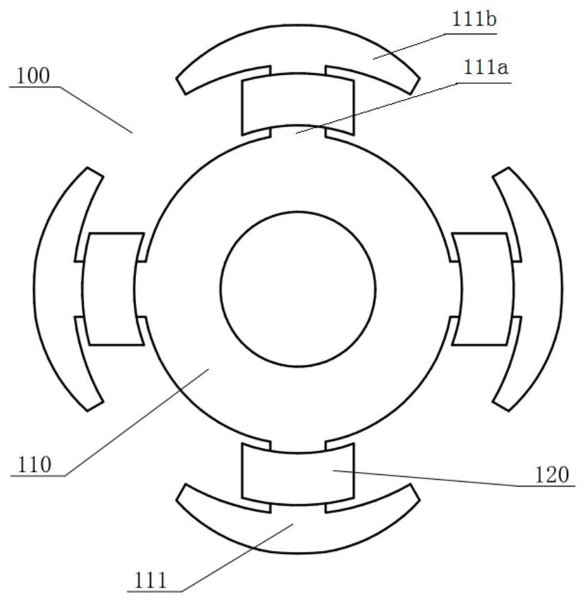
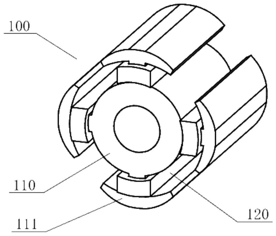
[0029] Figure 1-2What is shown is a structural schematic diagram of the induction rotor of the present invention. The induction rotor 100 includes a rotor core 110 and a conductive ring 120, the rotor core 110 is provided with a salient pole 111, the salient pole 111 is provided with a pole body 111a, and the conductive ring 120 is provided on the rotor 100 by surrounding the pole body 111a of the salient pole 111 superior. The salient poles 111 of the rotor core 110 are also provided with pole wings 111b, which are respectively connected to the left and right sides of the radially outer end of the pole body 111a. The pole wings 111b extend to the outside away from the pole body 111a, and The distance between the radially outer surface of the pole wing 111b and the center of the rotor core 110 in the extending direction changes gradually.

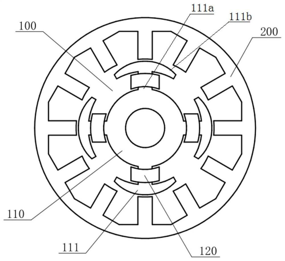
[0030] image 3 The shown switched reluctance motor applies the induction rotor 100 of this embodiment. The number of poles of the sta...

Embodiment 2

[0032] Figure 4 What is shown is another structural schematic diagram of the induction rotor of the present invention. The induction rotor 100 includes a rotor core 110 and a conductive ring 120, the rotor core 110 is provided with a salient pole 111, the salient pole 111 is provided with a pole body 111a, and the conductive ring 120 is provided on the rotor 100 by surrounding the pole body 111a of the salient pole 111 superior. The salient pole 111 of the rotor core 110 is also provided with a pole wing 111b, and the left and right sides of the radially outer end of the pole body 111a are respectively connected to the pole wing 111b, and the pole wing 111b and the pole body 111a form a pole body 111a high pole. The wing 111b is low and stepped, and the pole wing 111b extends to the outside away from the pole body 111a. The distance between the center of the rotor core 110 decreases in steps; the number of steps on the left and right sides of the pole body 111a is four resp...


PUM


Abstract

The invention discloses an induction type rotor and a switched reluctance motor, and belongs to the field of switched reluctance motors. The induction type rotor comprises a rotor core and a conducting ring, salient poles are arranged on the rotor core, pole bodies are arranged on the salient poles, and the conducting ring is arranged on the rotor by surrounding the pole bodies of the salient poles. The switched reluctance motor comprises a rotor and a stator, wherein the induction type rotor is adopted as the rotor. The conducting ring is arranged on the salient poles of the rotor core, induced current is generated by the conducting ring in the working process to form induced magnetic poles, and magnetic circuits are concentrated to the salient poles of the rotor, so that the magnetic energy utilization rate and the output torque are increased.

Description

technical field [0001] The invention relates to the field of switched reluctance motors, in particular to an induction rotor and a switched reluctance motor. Background technique [0002] The principle of the switched reluctance motor is that the magnetic circuit is always closed to the path with the smallest reluctance. The ideal magnetic circuit path is that the magnetic circuit starts from the energized salient pole of the stator core, passes through the air gap, and then passes through the salient pole of the rotor core. Then pass through the yoke of the rotor core, then pass through the salient poles of the rotor core, and then return to the energized salient poles of the stator core through the air gap; but due to the limitation of the iron core magnetization saturation and the characteristics of the magnetic circuit diverging outside the magnetic poles, some The magnetic circuit will deviate from the design path closure, and even generate reverse torque, resulting in ...

Claims


Application Information

Patent Timeline
Patent Type & Authority Applications(China)
IPC IPC(8): H02K1/14H02K1/24H02K29/03
CPCH02K1/146H02K1/24H02K1/246H02K29/03H02K2213/03
Inventor 顾志强李运忠刘正昂
Owner SHENZHEN HUAYIN POWER TECH CO LTD
Why Eureka
Try Eureka