Method and apparatus for isolating a wellhead for fracturing

a wellhead and isolating technology, applied in the direction of drilling casings, drilling pipes, borehole/well accessories, etc., can solve the problems of time and resource consumption, damage to the formation, and high cost of tools to rent and us

Active Publication Date: 2008-09-25
STREAM FLO INDS
View PDF16 Cites 26 Cited by
  • Summary
  • Abstract
  • Description
  • Claims
  • Application Information

AI Technical Summary

Benefits of technology

[0016]Preferably, the one or more wellhead members includes a tubing head and a tubing head adapter connected above the tubing head, the fracturing isolation tool seals in the vertical bore of the tubing head, the protector sleeve seals in the vertical bore of the adapter, and the pressure barrier profile is formed in the fracturing isolation tool at a location within the tubing head. In this way, when the fracturing isolation tool and the protector sleeve are sealed in the vertical bore, all seals and openings in the tubing head and the tubing head adapter are protected from the fracturing pressure and the fracturing fluid.

Problems solved by technology

In the prior art, these fracturing isolation tools generally seal inside the casing or on the bit guide in a manner which can restrict full bore access to the casing.
These tools are expensive to rent and to use.
However, this procedure can damage the formation.
Both of the above approaches require a service crew at the well, which is time and resource intensive.
Repetitive installation and removal of equipment adds to the costs of managing the wellhead.
However, a problem exists with the fracturing isolation sleeve of the Swagerty patent.
This exposure may damage the sealing surfaces and / or pressure barrier profile, preventing the pressure barrier from sealing after the fracturing process.

Method used


Image

  • Method and apparatus for isolating a wellhead for fracturing
  • Method and apparatus for isolating a wellhead for fracturing
  • Method and apparatus for isolating a wellhead for fracturing

Examples


first embodiment

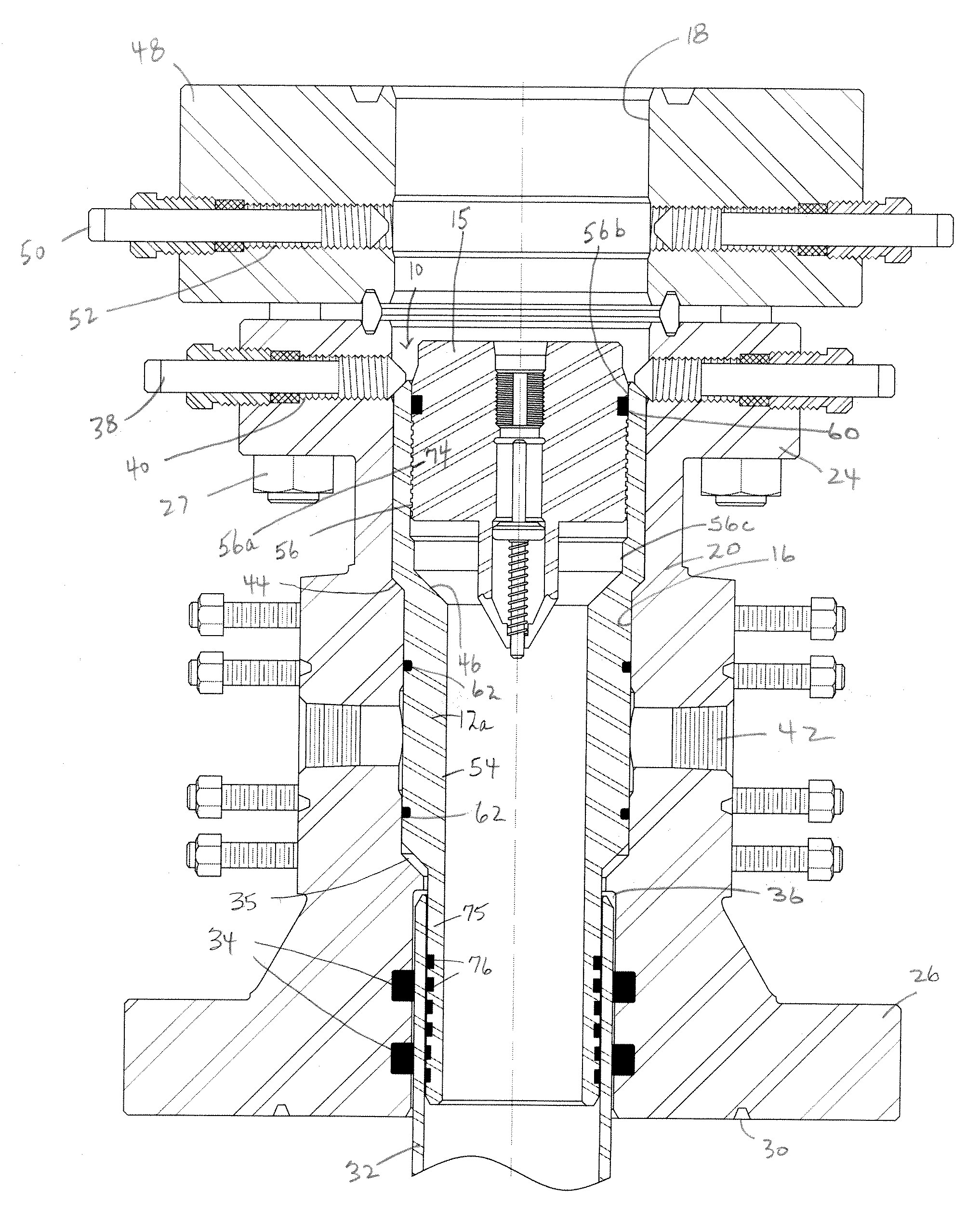
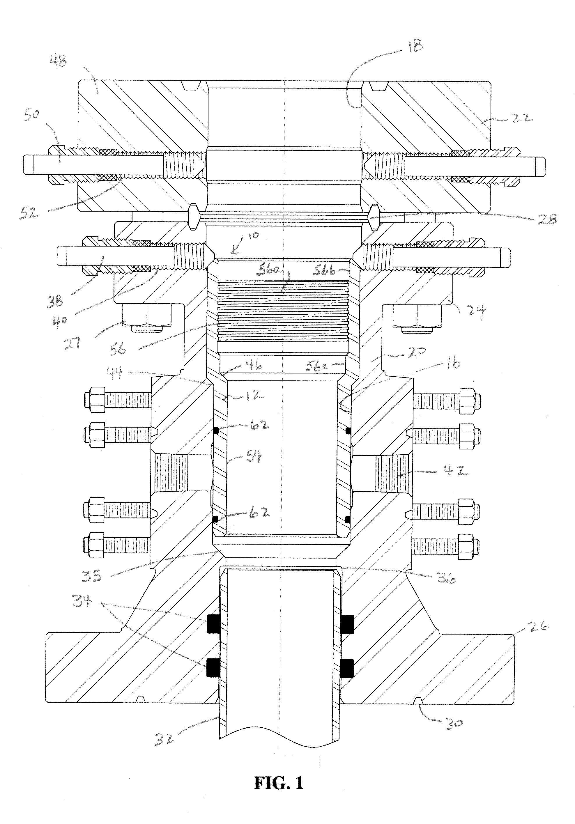
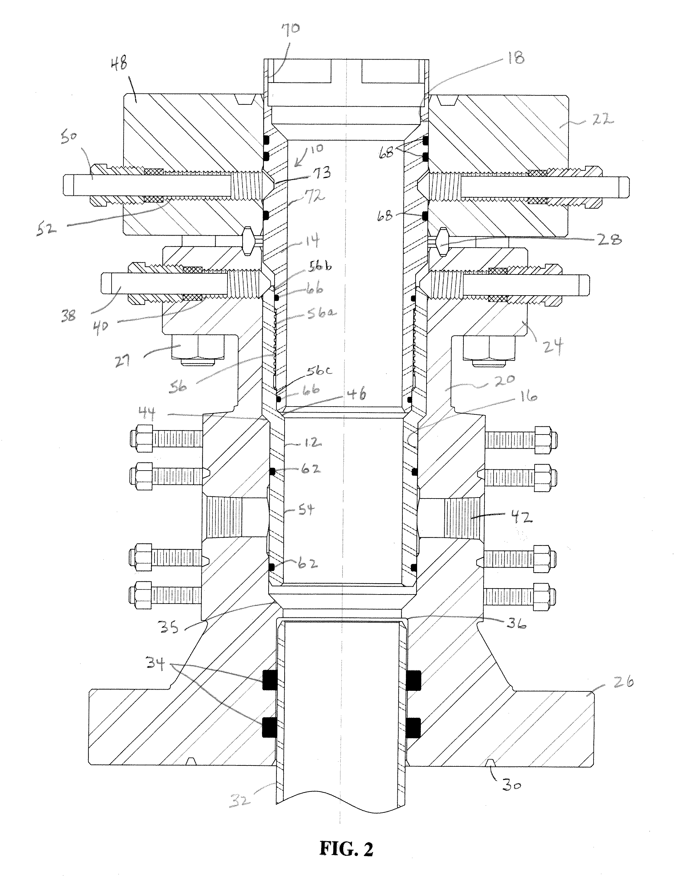
[0035]The fracturing isolation assembly 10 of this invention is shown in the figures as including a lower fracturing isolation tool 12 and an upper protector sleeve 14. The fracturing isolation tool 12 and protector sleeve 14 may be located within a wellhead composed of one or more wellhead body members, although in the embodiments shown herein the wellhead includes at least two connected wellhead body members. The fracturing isolation tool 12 and the protector sleeve 14 are shaped and sized so that, when engaged together in sealing relationship during fracturing within the wellhead, they combine to seal the vertical bore through the one or more wellhead body members in a manner such that all seals and openings in and between the wellhead members are protected from the fracturing pressure and the fracturing fluid. Turning to the figures, the fracturing isolation assembly 10 is shown in FIGS. 1-3 to be located in the vertical bores 16, 18 of a lower tubing head 20 and a tubing head a...

fourth embodiment

[0045]FIG. 10 illustrates the method and apparatus of the present invention, in which an interchangeable secondary seal bushing 82 is carried in a widened portion 83 of the vertical bore 16c at the lower end of the tubing head 20c for sealing to the production casing 32 and the fracturing isolation tool 12. The seal bushing 82 forms an inwardly extending bit guide 84 between its ends. Above the bit guide 84, the fracture isolation tool 12 carrier outer circumferential seal 86 to seal to the bore of the seal bushing 82. Below the bit guide 84, the seal bushing 82 carries outer secondary bushing casing seals 88 to the outer circumference of the production casing 32. The seal bushing 82 carries a plurality of outer circumferential seals 90 to the vertical bore 16 of the tubing head 20c. The seal bushing 82 is retained in the bore 16 at its lower end by bushing retainer 89. The interchangeable secondary seal bushing 82 allows for sealing to a wider range of casing environments. As can b...


PUM


Abstract

A welihead assembly to seal to a production casing including one or more pressure-containing wellhead body members defining a vertical bore, with the lowermost of the wellhead body members sealing to the production casing. A fracturing isolation tool is sealed in the vertical bore of the wellhead body members above the production casing, and forms a pressure barrier profile in its internal bore. A removable protector sleeve is located at least partially within the fracturing isolation tool to seal, protect, isolate and cover the pressure barrier profile against a fracturing pressure and a fracturing fluid. After fracturing the protector sleeve is removed and a pressure barrier is sealed in the pressure barrier profile of the fracturing isolation tool. The invention also extends to the method of isolating the wellhead body members and to the fracturing isolation tool assembly which includes the fracturing isolation tool and the protector sleeve.

Description

CROSS-REFERENCE TO RELATED APPLICATIONS[0001]This application claims priority from U.S. Provisional Patent Application No. 60 / 896,697, filed Mar. 23, 2007, which is incorporated by reference herein in its entirety to the extent that there is no inconsistency with the present disclosure.BACKGROUND OF THE INVENTION[0002]This invention relates to a method and apparatus for isolating a portion of a wellhead during a fracturing operation.[0003]One frequent well servicing technique for oil and gas formations having low permeability is to artificially “stimulate” to increase the permeability of the production zone(s). Generally, these stimulation techniques are referred to as “fracturing”. Fracturing involves pumping pressurized fluids through perforations in a well casing into a production zone in order to break or fracture pores in the production zone to improve permeability so that the hydrocarbon fluids can drain from the production zone into the casing. Fracturing generally involves f...

Claims


Application Information

Patent Timeline
Patent Type & Authority Applications(United States)
IPC IPC(8): E21B43/18
CPCE21B43/26E21B33/068E21B43/2607
Inventor LAM, TONY M.SCHNEIDER, KEVIN PAUL
Owner STREAM FLO INDS
Why Eureka
Try Eureka