Surgical Stapler and Method

a stapler and surgical technology, applied in the field of surgical instruments and methods, can solve the problems of biocompatible adhesives, primary disadvantages of tissue seam weakness, etc., and achieve the effects of reducing firing force, reducing manufacturing costs, and reducing the number of components

Inactive Publication Date: 2008-09-25
TYCO HEALTHCARE GRP LP
View PDF55 Cites 125 Cited by
  • Summary
  • Abstract
  • Description
  • Claims
  • Application Information

AI Technical Summary

Benefits of technology

[0044]The body tissue property reinforcing system is configured and adapted to deliver an amount of biocompatible wound closure material to the adjacent layers of body tissue to enhance the repairing or joining of the adjacent layers of body tissue to one another.
[0057]It is yet another object of the present disclosure to provide surgical stapling instruments for reducing or preventing leakage of fluid where body tissue has been repaired and / or joined by staples.
[0058]It is yet another object of the present disclosure to provide surgical stapling instruments for reducing or preventing bleeding where the body tissue has been repaired and / or joined by the staples.
[0060]It is still another object of the present disclosure to provide surgical staplers that can employ staples in combination with biocompatible wound closure materials, e.g., adhesives and / or electrocautery to improve the staple / tissue holding strength, healing patterns, sealing, hemostasis and long term patency of the staple line.
[0062]It is still a further object of the present disclosure to provide surgical staplers which are less expensive to manufacture, due to the reduced number of components, which require a reduced firing force and which allow a reduced criticality of manufacturing tolerances of some of the components of the surgical staplers.

Problems solved by technology

Despite these advantages, however, the weakness along the tissue seam remains as a primary disadvantage in the use of biocompatible adhesives.

Method used


Image

  • Surgical Stapler and Method
  • Surgical Stapler and Method
  • Surgical Stapler and Method

Examples


Embodiment Construction

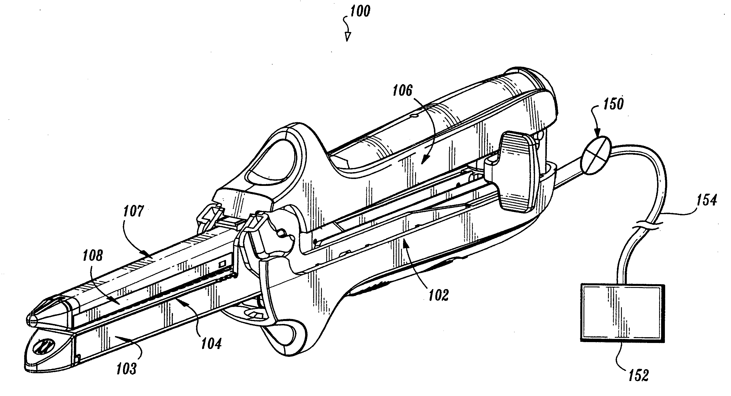
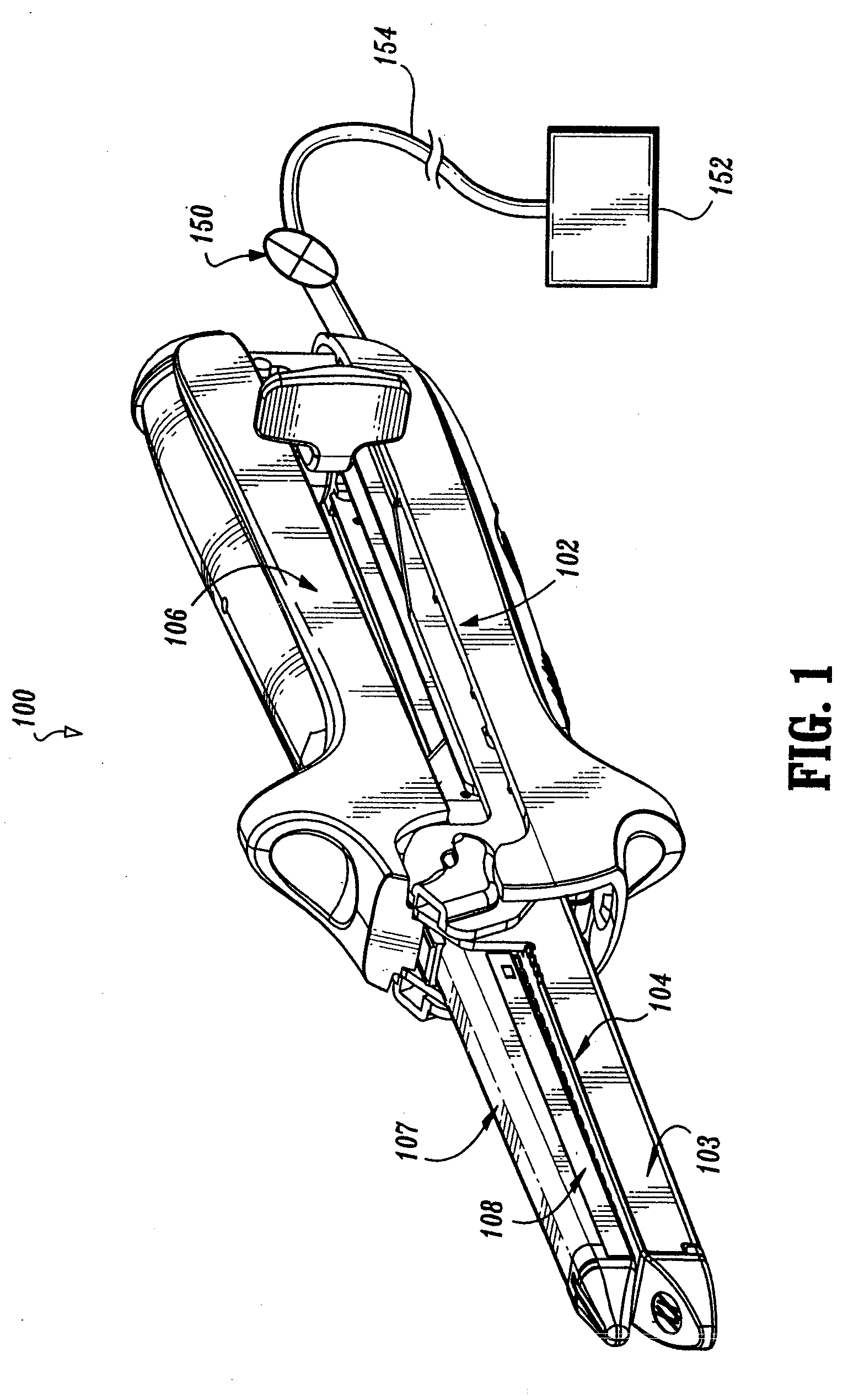
[0077]Preferred embodiments of the presently disclosed surgical stapler will now be described in detail with reference to the drawing figures wherein like reference numerals identify similar or identical elements. As used herein and as is traditional, the term “distal” refers to that portion which is further from the user while the term “proximal” refers to that portion which is closer to the user.

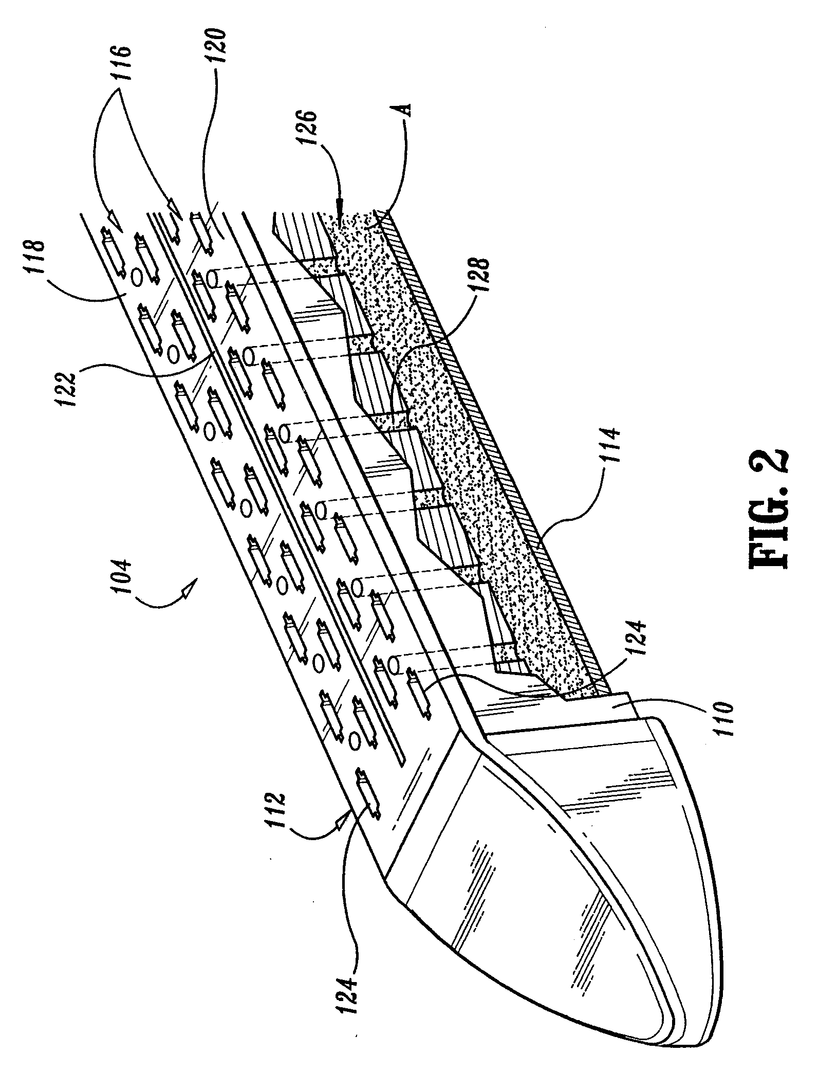
[0078]There are several known types of surgical staplers for various procedures with each stapler including a staple anvil and staple cartridge which are adjustably approximated relative to each other. A typical staple cartridge usually has at least two laterally spaced rows of staple slots and staples therein for mechanically joining adjacent layers of tissue to one another. The staple anvil likewise usually includes two rows of staple forming depressions formed therein which are aligned with the rows of staples slots in the cartridge. In use, each of the surgical staplers involves grippi...


PUM

PropertyMeasurementUnit
volumeaaaaaaaaaa
biocompatibleaaaaaaaaaa
timeaaaaaaaaaa

Abstract

The present disclosure relates to surgical instruments including a staple anvil formed in a distal end of the surgical stapler and a staple cartridge selectively receivable in a distal end of the surgical stapler and in juxtaposition relative to the staple anvil, the staple cartridge including one or more laterally spaced apart rows of staple slots formed in an upper surface thereof, a plurality of surgical staples disposed, one each, within the staple slots, and a staple line reinforcing system configured and adapted to augment the strength of the staple line formed by the firing of the surgical staples into body tissue, wherein the surgical stapler concomitantly drives the plurality of surgical staples through the adjacent layers of body tissue to mechanically secure the body tissue and activates the reinforcing system to non-mechanically secure the adjacent layers of body tissue to one another.

Description

CROSS-REFERENCE TO RELATED APPLICATION[0001]The present application claims the benefit of and priority to U.S. Provisional Application Ser. No. 60 / 373,224 filed on Apr. 16, 2002, the entire contents of which are incorporated herein by reference.BACKGROUND[0002]1. Technical Field[0003]The present disclosure relates to surgical instruments and methods for enhancing properties of tissue repaired or joined by surgical staples and, more particularly to surgical instruments configured to apply surgical mechanical fasteners concomitantly with a non-mechanical biocompatible wound closure material to enhance the properties of repaired or adjoined tissue at a target surgical site.[0004]2. Discussion of Related Art[0005]Throughout the years the medical field has utilized various techniques in an effort to join or bond body tissue together. Historically, suturing was the accepted technique for rejoining severed tissues and closing wounds. Suturing was historically achieved with a surgical needl...

Claims


Application Information

Patent Timeline
Patent Type & Authority Applications(United States)
IPC IPC(8): A61B17/04A61B17/00A61B17/068A61B17/072A61B17/115A61B18/14
CPCA61B17/00491A61B17/04A61B17/0686A61B17/07207A61B17/07292A61B2018/1425A61B17/1155A61B18/1442A61B18/1477A61B2017/07214A61B2017/07278A61B17/115
Inventor HEINRICH, RUSSELL
Owner TYCO HEALTHCARE GRP LP
Why Eureka
Try Eureka