Hydroelectric generator turbine flow guide structure

Inactive Publication Date: 2008-09-25
WEN CHANG TING
View PDF3 Cites 23 Cited by
  • Summary
  • Abstract
  • Description
  • Claims
  • Application Information

AI Technical Summary

Benefits of technology

[0018]In comparison with prior arts, the flow guide base of the base of the hydroelectric generator turbine flow guide structure includes at least one jet nozzle for introducing the water flow to the turbine, and

Problems solved by technology

However, if water pressure is insufficient, or the fall of the water does not create enough power, the hydroelectric generation cannot provide a sufficient amount of electricity.
Therefore, a larger water pressure will

Method used


Image

  • Hydroelectric generator turbine flow guide structure
  • Hydroelectric generator turbine flow guide structure
  • Hydroelectric generator turbine flow guide structure

Examples


Embodiment Construction

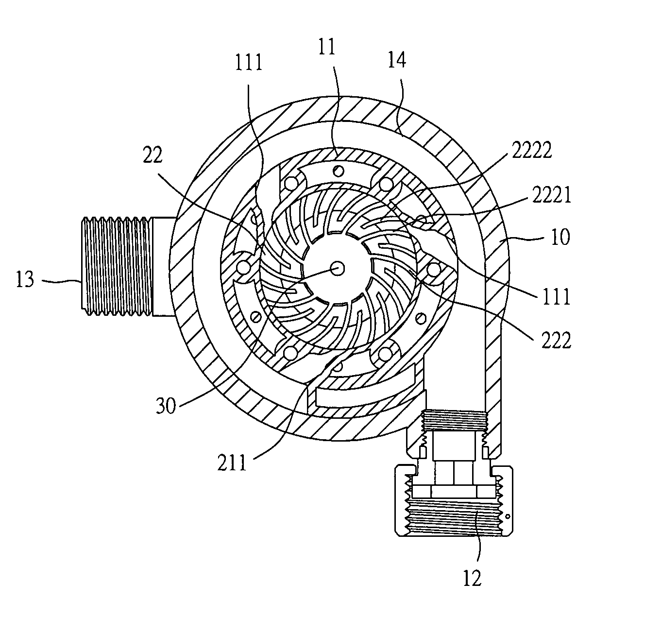
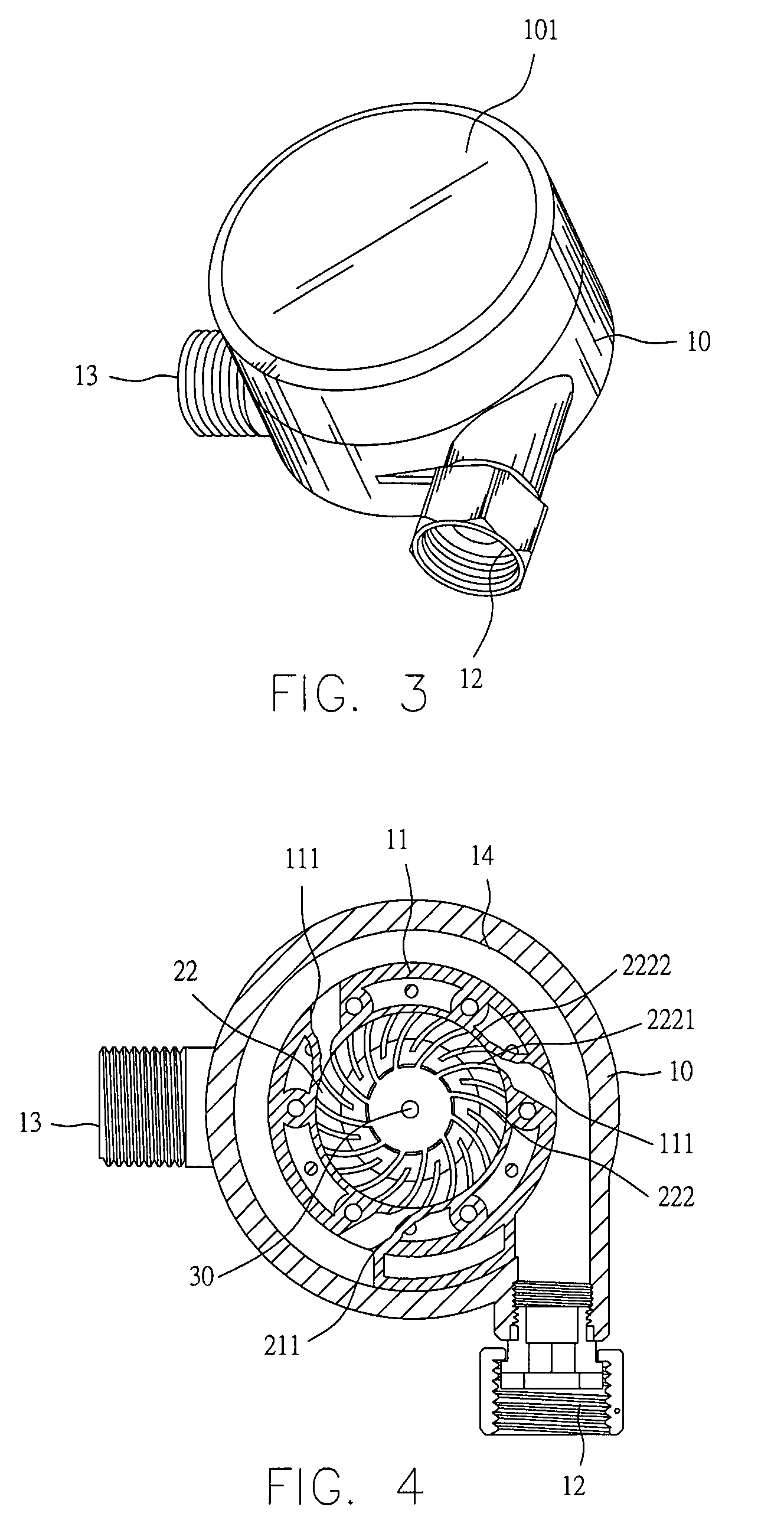
[0029]Referring to FIGS. 3 through 5, a hydroelectric generator turbine flow guide structure in accordance with the present invention includes a turbine 22 arranged in a base 10. Power of the turbine 22 is transmitted to a generator 40 via a power transmission member 30 (in this embodiment, the power transmission member 30 is an axle). After the turbine 22 and the power transmission member 30 are rotated, the power is transmitted to the generator 40 for generating electricity.

[0030]Referring again to FIG. 3, the base 10 is of a round box-like shape that fits with a profile of the turbine 22, and forms a top cover 101 at a top thereof for allowing removal, replacement or repair of internal components, and the base 10 forms an inlet port 12 and an outlet port 13 for allowing water to flow into and out of the base 10, and a flow guide passage 14 for allowing the water to flow. The inlet port 12 and the outlet port 13 are located in different planes. In this embodiment, the inlet port 1...


PUM


Abstract

The present invention discloses a hydroelectric generator turbine flow guide structure. The turbine is arranged in a base, and the base includes an inlet port and an outlet port for allowing water to flow into and out of the base, and a flow guide passage for allowing the water to flow; power of the turbine is transmitted to a generator via a power transmission member, the base includes a flow guide base and the turbine arranged on the flow guide base; wherein the flow guide base includes at least one jet nozzle for introducing the water flow to the turbine, and the at least one jet nozzle has a diameter gradually decreasing along a direction from the base toward the turbine. The hydroelectric generator turbine flow guide structure of the present invention takes the most advantage of the water pressure and reduces pressure loss of the flow.

Description

BACKGROUND OF THE INVENTION[0001]1. Field of the Invention[0002]The present invention relates to a hydroelectric generator structure, and more particularly, to a hydroelectric generator turbine flow guide structure.[0003]2. Description of Related Art[0004]Currently, regarding ways of power generation, the hydroelectric generation is most environment-friendly and causes no pollution. However, if water pressure is insufficient, or the fall of the water does not create enough power, the hydroelectric generation cannot provide a sufficient amount of electricity.[0005]Referring to FIGS. 1 and 2, which illustrate a structure of a conventional small-scale hydroelectric generator, a turbine 90 is located in a base 80. An axle of the turbine 90 is connected with a generator (not labelled) via a power transmission member 91, so that the turbine 90, after being rotated, transmits power to the generator for generating electricity. The base 80 forms thereon an outlet port 81 and an inlet port 82...

Claims


Application Information

Patent Timeline
IPC IPC(8): F03B13/00
CPCF03B13/00
Inventor WEN, CHANG TING
Owner WEN CHANG TING
Why Eureka
Try Eureka