Slide Rail Unit With Retaining Function

Active Publication Date: 2008-09-25
THK CO LTD
View PDF8 Cites 30 Cited by
  • Summary
  • Abstract
  • Description
  • Claims
  • Application Information

AI Technical Summary

Benefits of technology

[0018]Thus, when the second rails makes a stroke movement with respect to the first rail, and the cam member gradually overlaps the pin guide member, the retaining pin is detached from the standby position of the pin guide member, and is caught by the cam member, with the second rail being pulled toward the stroke end by the urging force of the elastic member. As a result, it is possible to automatically draw in the second rail with respect to the first rail and to maintain the drawn-in state.
[0019]At this time, the retaining pin, which has been set at the standby position, solely undergoes

Problems solved by technology

Further, unless the roller climbs over the plate spring in the opposite direction, the inner rail cannot be drawn out of the

Method used


Image

  • Slide Rail Unit With Retaining Function
  • Slide Rail Unit With Retaining Function
  • Slide Rail Unit With Retaining Function

Examples


Embodiment Construction

[0035]In the following, a slide rail unit of the present invention will be described in detail with reference to the accompanying drawings.

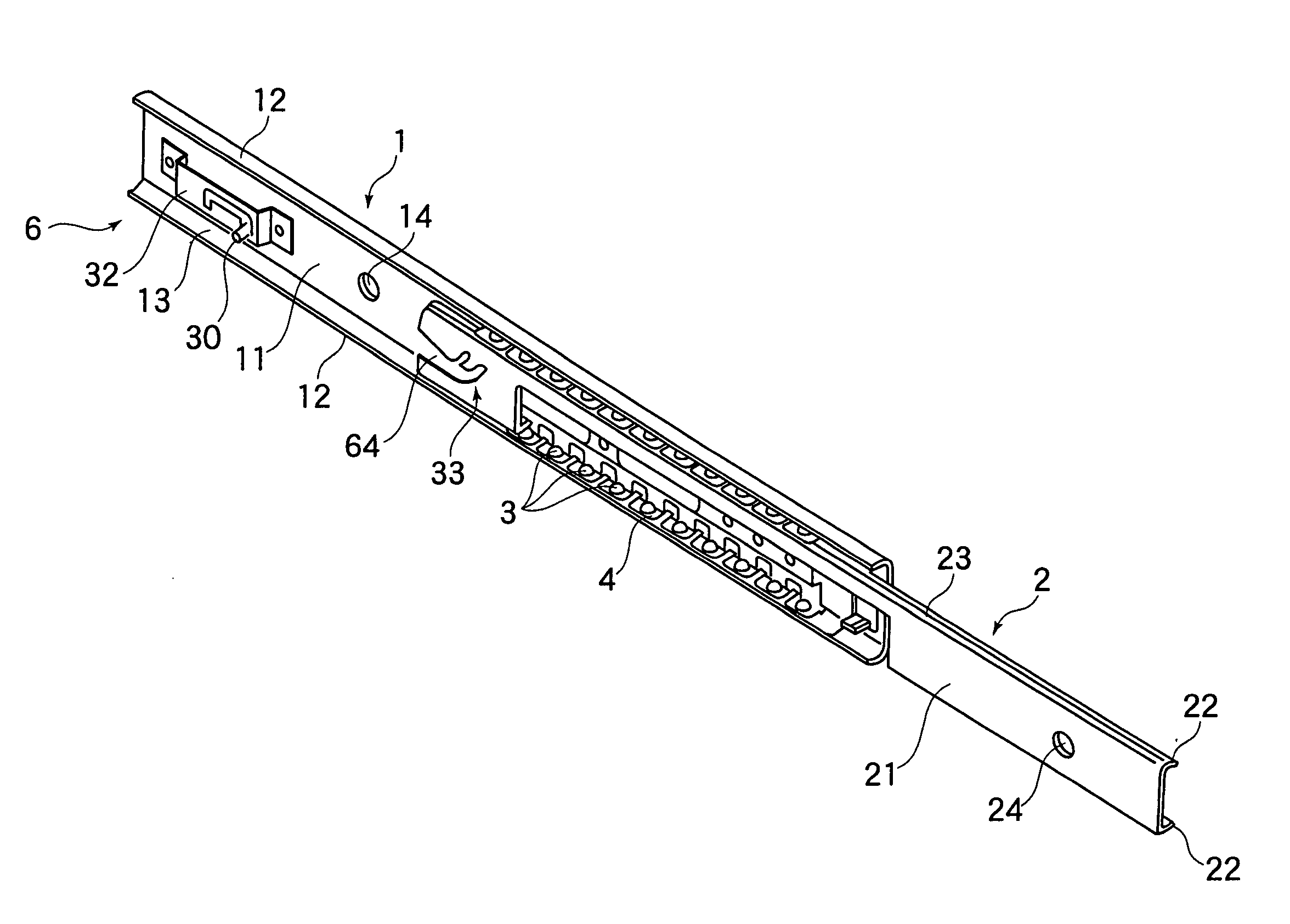
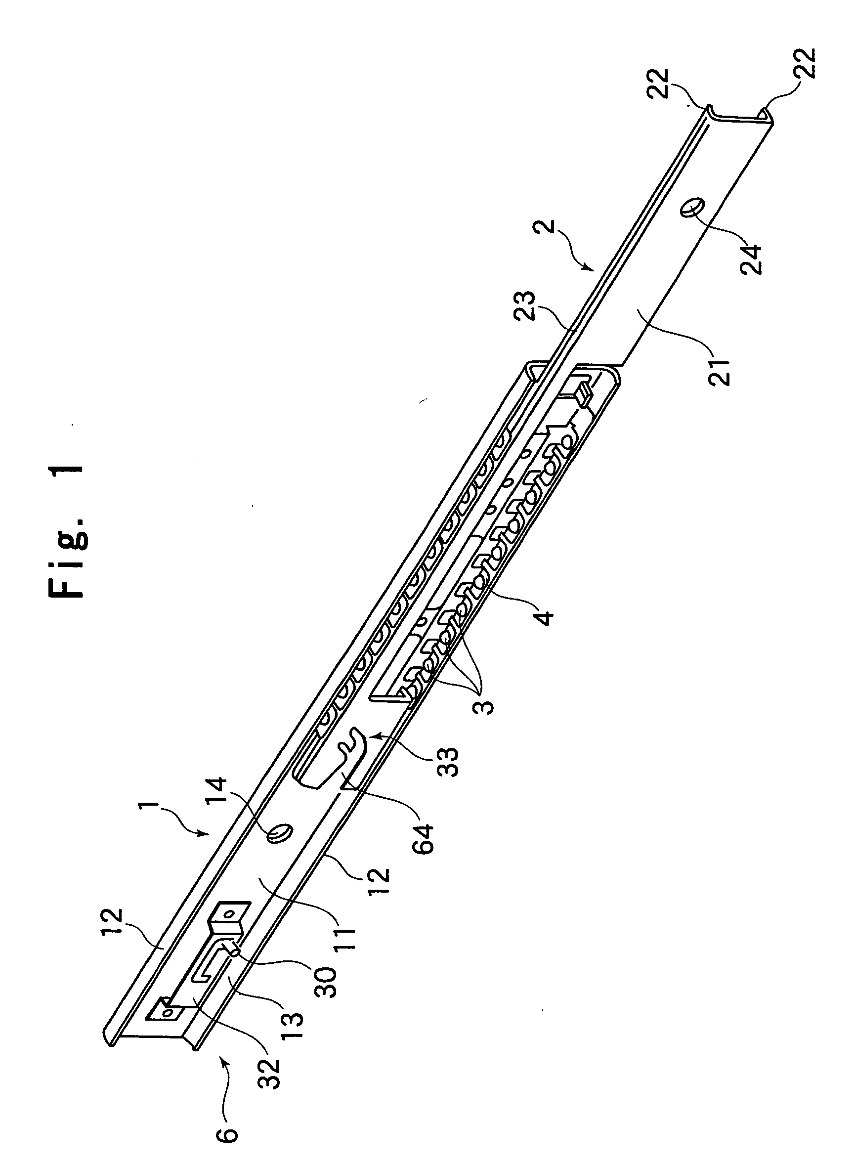
[0036]FIG. 1 shows a slide rail unit according to an embodiment of the present invention. The slide rail unit is composed of an outer rail 1, an inner rail 2 accommodated in the outer rail 1, balls 3 serving as rolling members rolling between the outer rail 1 and the inner rail 2, and a retainer 4 for aligning a large number of balls 3 at predetermined intervals between the outer rail 1 and the inner rail 2.

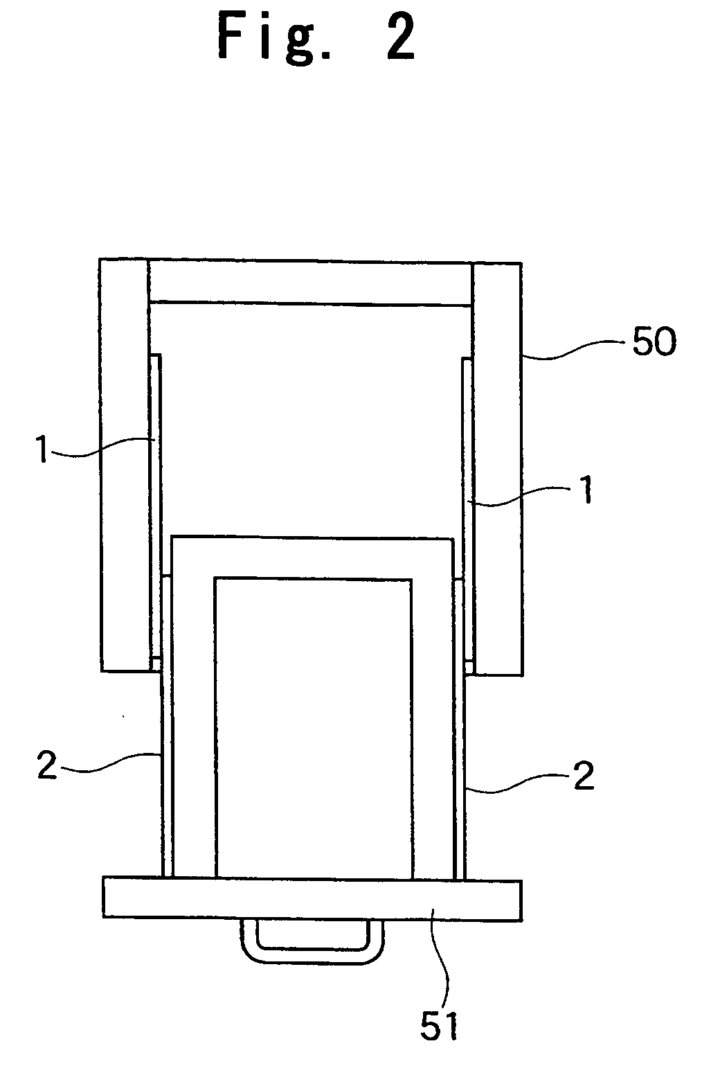
[0037]As shown, for example, in FIG. 2, the slide rail unit is used as a slide mechanism of a drawer 51 associated with a furniture main body 50. The outer rail 1 is fixed to the furniture main body 50, and the inner rail 2 is fixed to the drawer 51, making it possible for the drawer 51 to be smoothly drawn into and out of the furniture main body 50.

[0038]The outer rail 1 is precision-shaped by roll forming of a steel plate, and it is formed i...


PUM


Abstract

Provided is a slide rail unit which, when accommodating a second rail (2) in a first rail (1), can automatically draw in the second rail to an end position and retain it at that position and which can be produced easily with a small number of parts and at low cost, the slide rail unit being equipped with a retaining pin (30) provided upright so as to be movable with respect to the first rail (1) in the longitudinal direction and the width direction thereof, an elastic member (31) for urging the retaining pin (30) toward the stroke end of the second rail (2), a pin guide member (32) provided on the first rail (1) and adapted to lock the retaining pin (30) at a standby position spaced apart from the stroke end against an urging force of the elastic member (31) and to guide the retaining pin (30) detached from the standby position toward the stroke end with the urging force, and a cam member (33) provided on the second rail (2) and adapted to detach the retaining pin (30) from the standby position of the pin guide member (32) and lock the retaining pin as it overlaps the pin guide member (32).

Description

TECHNICAL FIELD[0001]The present invention relates to a slide rail unit which is provided between a pair of members making relative reciprocation along a predetermined direction, as in the case of a drawer of a piece of furniture or a paper tray of a copying machine, for supporting a relative advancing / retreating movement of these members, and in particular, to a slide rail unit which, at a stroke end of such the advancing / retreating movement, can urge a movable member toward the stroke end and retain the movable member at the stroke end position.BACKGROUND ART[0002]Up to now, as a guide member for supporting an advancing / retreating movement of a movable member, such as a drawer in a piece of furniture or a system kitchen, there is known a slide rail unit equipped with an outer rail and an inner rail (see JP 11-201158 A, etc.). More specifically, the conventional slide rail unit is composed of an outer rail formed into a channel-like shape by bending and raising a pair of ball rolli...

Claims


Application Information

Patent Timeline
IPC IPC(8): A47B88/16
CPCA47B88/047A47B88/467
Inventor HOSHIDE, KAORUSATO, AKIRASASAKI, SOICHI
Owner THK CO LTD
Why Eureka
Try Eureka