Methods of Performing Error Concealment For Digital Video
What is Al technical title?
Al technical title is built by PatSnap Al team. It summarizes the technical point description of the patent document.
a technology of error concealment and digital video, applied in the field of digital video decoding and display, can solve the problems of information loss, degraded wireless signals, information loss, etc., and achieve the effect of high-quality digital video error concealmen
Inactive Publication Date: 2008-09-25
QUALCOMM INC
View PDF8 Cites 59 Cited by
Summary
Abstract
Description
Claims
Application Information
AI Technical Summary
This helps you quickly interpret patents by identifying the three key elements:
Problems solved by technology
Method used
Benefits of technology
[0011]The present invention introduces methods for performing error concealment when errors are detected within digital video in
Problems solved by technology
Although these new digital wireless protocols are designed to be resistant to errors, digital wireless communication is always subject to information loss due to various physical effects on the wireless signals.
For example, radio interference, errors caused by multi-path reflections, radio signal shielding, range limitations, and other problems can degrade transmitted wireless signals such that information becomes lost.
When some information is lost during the transmission of the digital video, there is not enough time to request and receive a retransmission of the lost information since retransmission brings significant delay which is not suitable for real-time applications such as video telephony and video streaming.
Thus, when digital video information is lost, the digital video receiver must attempt to display one ore more video frames using the received incomplete digital video information.
Method used
Image
Click on the blue label to locate the original text in one second.
Reading with bidirectional positioning of images and text.
Examples
case 1
[0088] Case 1 requires that at least one of the adjacent three pixels in three neighboring macroblocks (below, right, and lower right) be available. Specifically, referring to FIG. 6A, one of area F's three closest neighbors α, β and γ must be in a non-corrupt macroblocks. Case 1 is further divided into the following four sub-cases 1.1 to 1.4:
case 1.1
[0089] Case 1.1 occurs when all of the three surrounding pixels α, β and γ are available (all of the pixels are in non-corrupt macroblocks). When three surrounding pixels α, β and γ are available, then the corner pixel of area F is reconstructed using the median adaptive predictor with:
[0090]The original median adaptive predictor, designed to compress images losslessly, is a nonlinear predictor to predict a current pixel x by three surrounding pixels p, q and r as illustrated in FIG. 6B. It assumes that a vertical edges lies above x if r≧q ≧p or r≦q≦p, and a horizontal edge lies above x if r≧p≧q or r≦p≦q. Note that the three surrounding pixels used to reconstruct area F are different from those in the original median adaptive predictor.
case 1.2
[0091] Case 1.2 is used when both pixels α and β of FIG. 6A are in non-corrupt macroblocks (but γ is not available since that would be case 1.1). In case 1.2, the corner pixel of area F is reconstructed using pixel averaging with the following equation:
x(15,15)=(x(16,15)+x(15,16)+1)2(13)
wherein the divide by two operation may be performed with a shift right operation (>>1).
PUM
Abstract
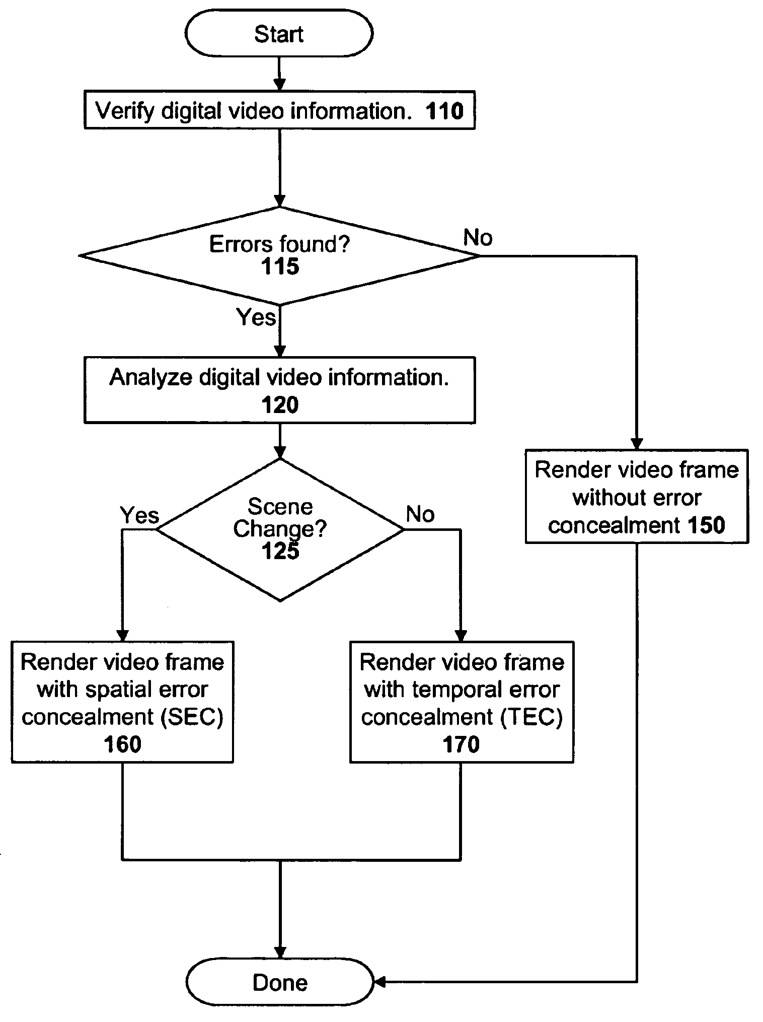
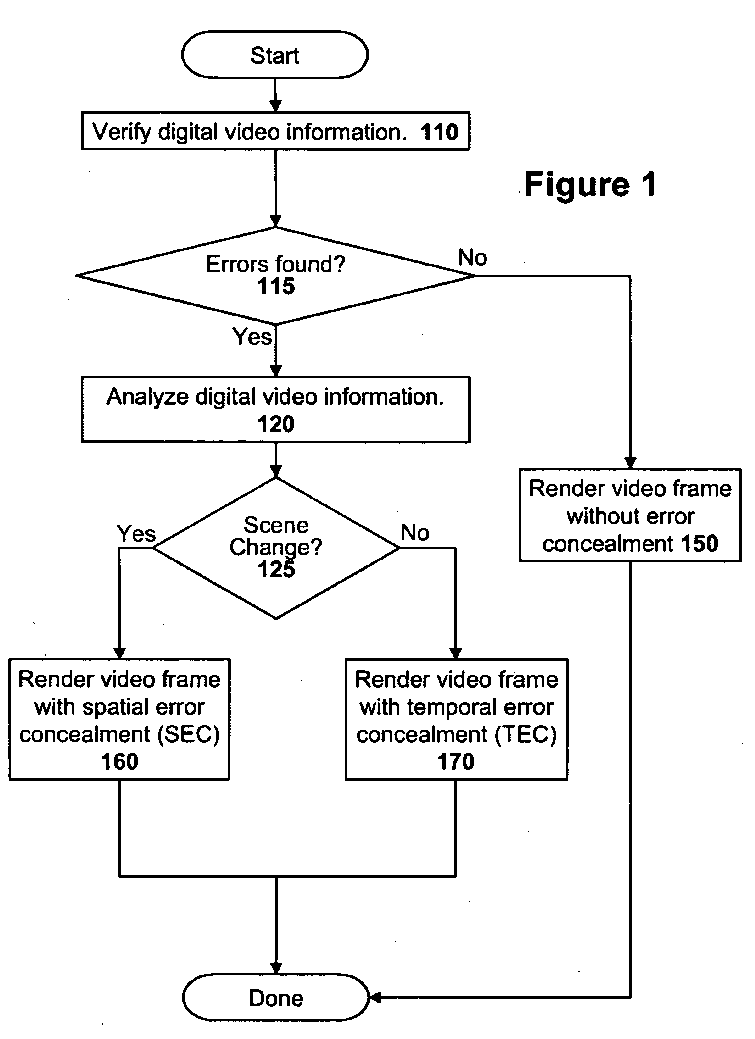
Error concealment is used to hide the effects of errors detected within digital video information. A complex error concealment mode decision is disclosed to determine whether spatial error concealment (SEC) or temporal error concealment (TEC) should be used. The error concealment mode decision system uses different methods depending on whether the damaged frame is an intra-frame or an inter-frame. If the video frame is an intra-frame then a similarity metric is used to determine if the intra-frame represents a scene-change or not. If the video frame is an intra-frame, a complex multi-termed equation is used to determine whether SEC or TEC should be used. A novel spatial error concealment technique is disclosed for use when the error concealment mode decision determines that spatial error concealment should be used for reconstruction. The novel spatial error concealment technique divides a corrupt macroblock into four different regions, a corner region, a row adjacent to the corner region, a column adjacent to the corner region, and a remainder main region. Those regions are then reconstructed in that order and information from earlier reconstructed regions may be used in later reconstructed regions. Finally, a macroblock refreshment technique is disclosed for preventing error propagation from harming non-corrupt inter-blocks. Specifically, an inter-macroblock may be ‘refreshed’ using spatial error concealment if there has been significant error caused damage that may cause the inter-block to propagate the errors.
Description
FIELD OF THE INVENTION[0001]The present invention relates to the field of digital video decoding and display. In particular the present invention discloses techniques for concealing errors in digital video caused by damaged or lost digital video information.BACKGROUND OF THE INVENTION[0002]There has been a wirelesselectronics revolution in recent years due to the rapid advancements and adoption of many new digital wireless communication protocols. For example, Code Division Multiple Access (CDMA) and Global System for Mobile communication (GSM) have greatly increased the popularity of digital cellular telephones, Wi-Fi local area network (LAN) protocols (such as 802.11b, 802.11g, 802.11a, etc.) have revolutionized wireless computer networks, and Bluetooth has provided a very useful short range wireless digital protocol for many different digital devices.[0003]Although these new digital wireless protocols are designed to be resistant to errors, digital wireless communication is alwa...
Claims
Application Information
Patent Timeline
Application Date:The date an application was filed.
Publication Date:The date a patent or application was officially published.
First Publication Date:The earliest publication date of a patent with the same application number.
Issue Date:Publication date of the patent grant document.
PCT Entry Date:The Entry date of PCT National Phase.
Estimated Expiry Date:The statutory expiry date of a patent right according to the Patent Law, and it is the longest term of protection that the patent right can achieve without the termination of the patent right due to other reasons(Term extension factor has been taken into account ).
Invalid Date:Actual expiry date is based on effective date or publication date of legal transaction data of invalid patent.