
Camera monitor

a technology for monitors and cameras, applied in the field of cameras, can solve the problems of unpredictability, inconvenient, complicated, and expensive, and achieve the effect of widening the visual angle and being assembled easily

Inactive Publication Date: 2008-09-25
LAI DAVID
View PDF12 Cites 0 Cited by
  • Summary
  • Abstract
  • Description
  • Claims
  • Application Information

AI Technical Summary

Benefits of technology

[0007]The main object of the present invention is to provide a camera monitor with a reflecting mirror for obtaining a wider visual angle, and the camera monitor is structurally simple and can be assembled easily.

Problems solved by technology

It is most dreadful when people confront danger in deserted places.
Some accidental situations people may encounter, such as stealing, robbing, or disputing, usually occur unpredictably in deserted places.
No matter what the way people might adopt, it is inconvenient, complicated, and costly.

Method used


Image

  • Camera monitor
  • Camera monitor
  • Camera monitor

Examples


Embodiment Construction

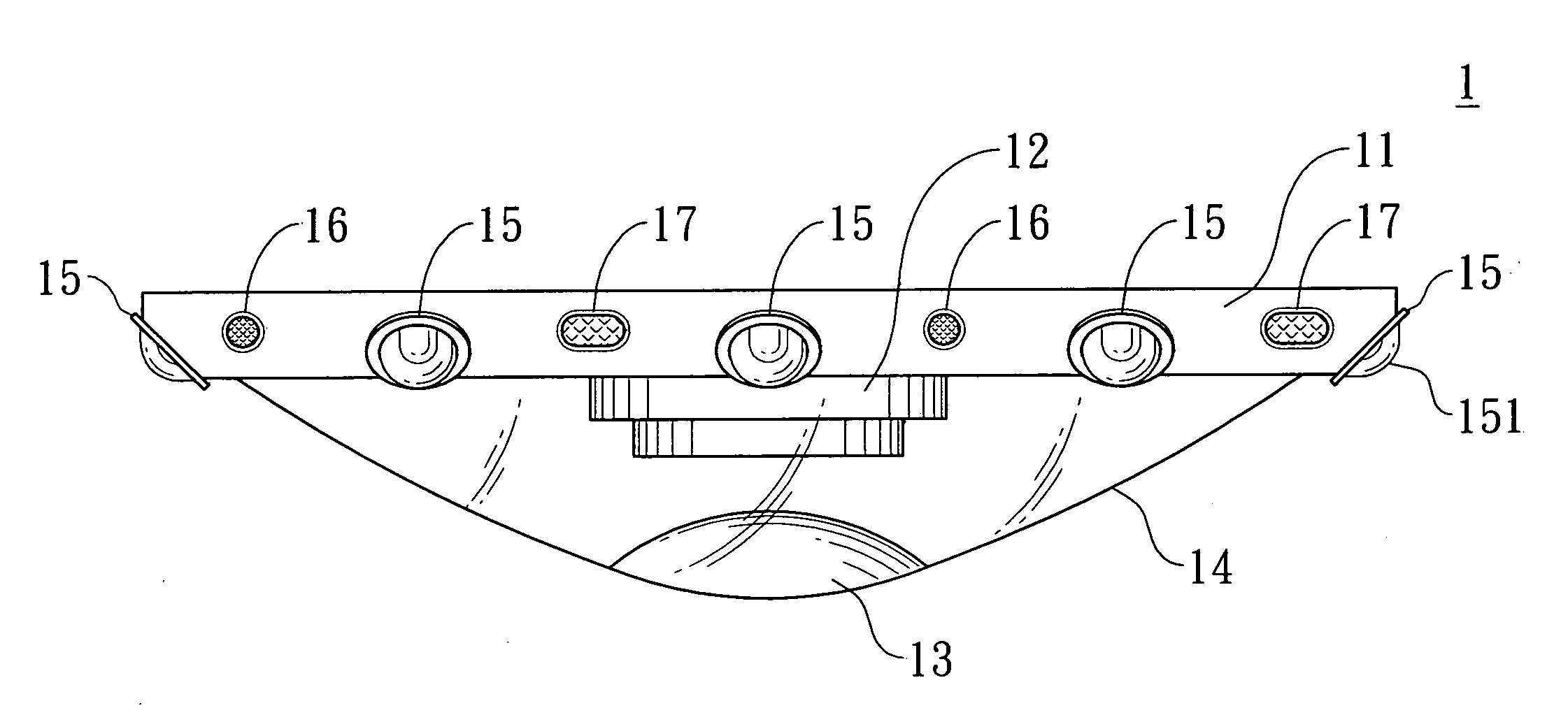
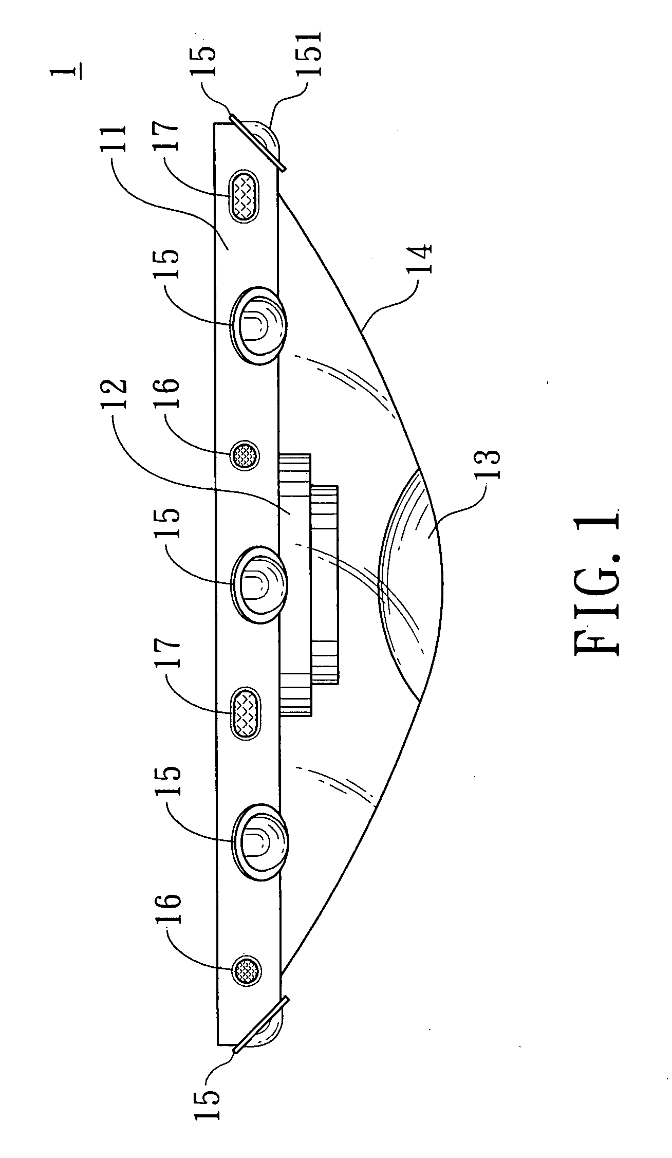
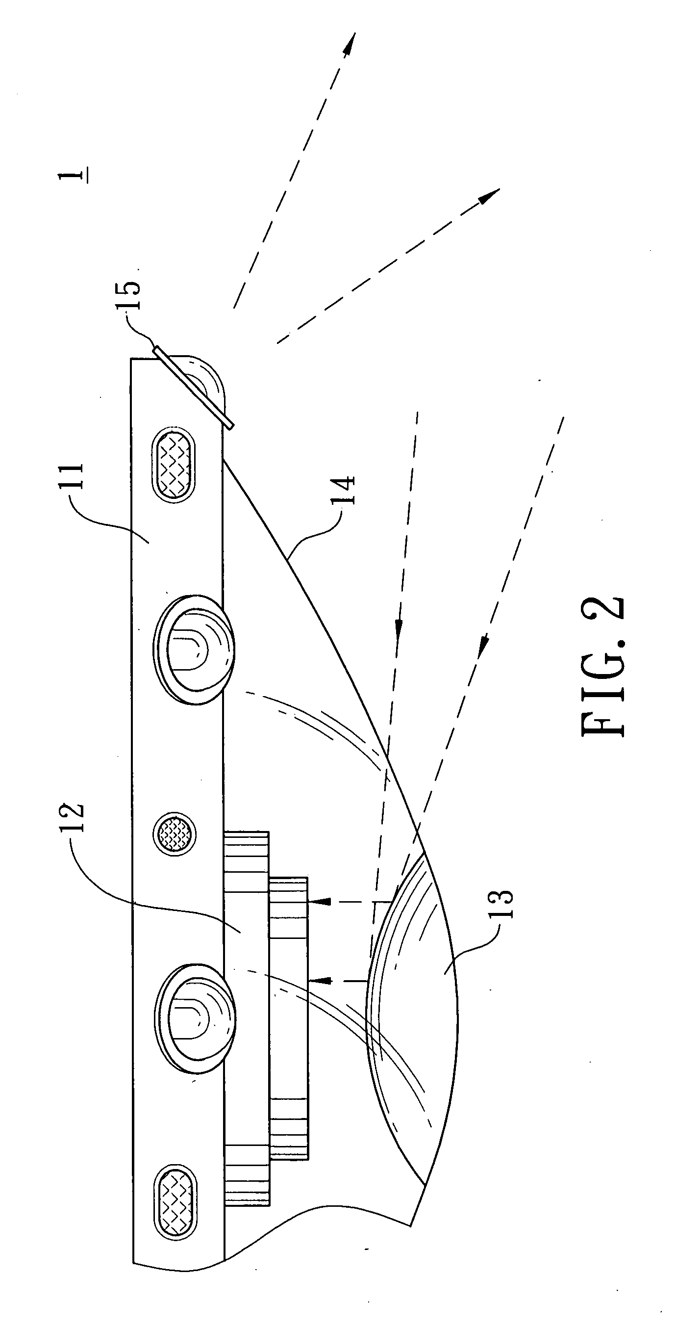
[0014]Referring to FIGS. 1 and 2, these figures show a preferred embodiment of a camera monitor 1 according to the present invention, wherein the camera monitor 1 comprises a main body 11, a camera device 12, and a reflecting mirror 13.

[0015]The main body 11 has a cover 14 pervious to light and is provided with at least a light 15 thereon for illumination. The light 15 includes a light-diverting shield 151 for preventing light from being reflected to lens of the camera 12 and focusing light. The camera device 12 is disposed within the main body 11 and covered by the cover 14. The reflecting mirror 13 is disposed on the cover at the location 14 that corresponds to the camera lens within the main body 11 so that an image outside the main body 11 can be reflected by the reflecting mirror 13 to the camera lens.

[0016]Moreover, as shown in FIG. 1, at least an audio-frequency receiver 16 and at least a speaker 17 are disposed alternately on the main body 11 so that sound information can be...


PUM


Abstract

A camera monitor comprises a main body, a camera device, and a reflecting mirror, wherein the main body has a cover pervious to light and is provided with at least a light thereon for illumination. The camera device is disposed within the main body and covered by the cover. The reflecting mirror is disposed on the cover at the location that corresponds to the camera lens within the main body so that an image outside the main body can be reflected by the reflecting mirror to the camera lens.

Description

BACKGROUND OF THE INVENTION[0001]1. Field of the Invention[0002]The present invention relates to a camera monitor, and more particularly, to a camera monitor that can be used for illumination and image monitor simultaneously, has a reflecting mirror for providing a wider visual angle, and is structurally simple and assembled easily so that it can be applicable for illuminating, monitoring, and recording in various public places or public transportation vehicles.[0003]2. Description of the Prior Art[0004]It is most dreadful when people confront danger in deserted places. Some accidental situations people may encounter, such as stealing, robbing, or disputing, usually occur unpredictably in deserted places. Thus, an optical monitor system is commonly provided for visualizing and monitoring these accidental situations in time for people reacting to and handle these situations as quickly as possible.[0005]In addition to the requirement and application of a monitor system for home securi...

Claims


Application Information

Patent Timeline
Patent Type & Authority Applications(United States)
IPC IPC(8): G03B15/00H04N5/238
CPCG03B15/035G03B17/17G03B37/06H04N5/23238G08B13/19626H04N5/2259G08B13/19619H04N23/58H04N23/698
Inventor LAI, DAVID
Owner LAI DAVID
Learn More