Relay finder optical system of an single-lens reflex camera

a single-lens reflex and optical system technology, applied in the field of single-lens reflex optical system of relay finder optical system, can solve the problems of large diameter complicated structure of lupe (magnifying) optical system, and shorter reli

Inactive Publication Date: 2008-09-25
RICOH IMAGING COMPANY
View PDF13 Cites 2 Cited by
  • Summary
  • Abstract
  • Description
  • Claims
  • Application Information

AI Technical Summary

Benefits of technology

[0008]The present invention provides a relay finder optical system of an SLR camera, in which aberrations can be well corrected and further miniaturization can be achieved, while securing a necessary eye relief, an apparent visual angle, and a finder magnification.

Problems solved by technology

On the other hand, in order to increase the magnification of the finder optical system, the focal length of the Lupe (magnifying) optical system is inevitably made shorter; and as a result, the eye relief becomes shorter, the diameter of the Lupe (magnifying) optical system becomes larger, and the structure of the Lupe (magnifying) optical system is complicated.
Conversely, if an attempt is made to enlarge the magnification of the relay finder optical system, not only the relay finder optical system but also the Lupe (magnifying) optical system is inevitably enlarged, so that the finder optical system (camera) cannot be miniaturized.

Method used


Image

  • Relay finder optical system of an single-lens reflex camera
  • Relay finder optical system of an single-lens reflex camera
  • Relay finder optical system of an single-lens reflex camera

Examples


embodiment 1

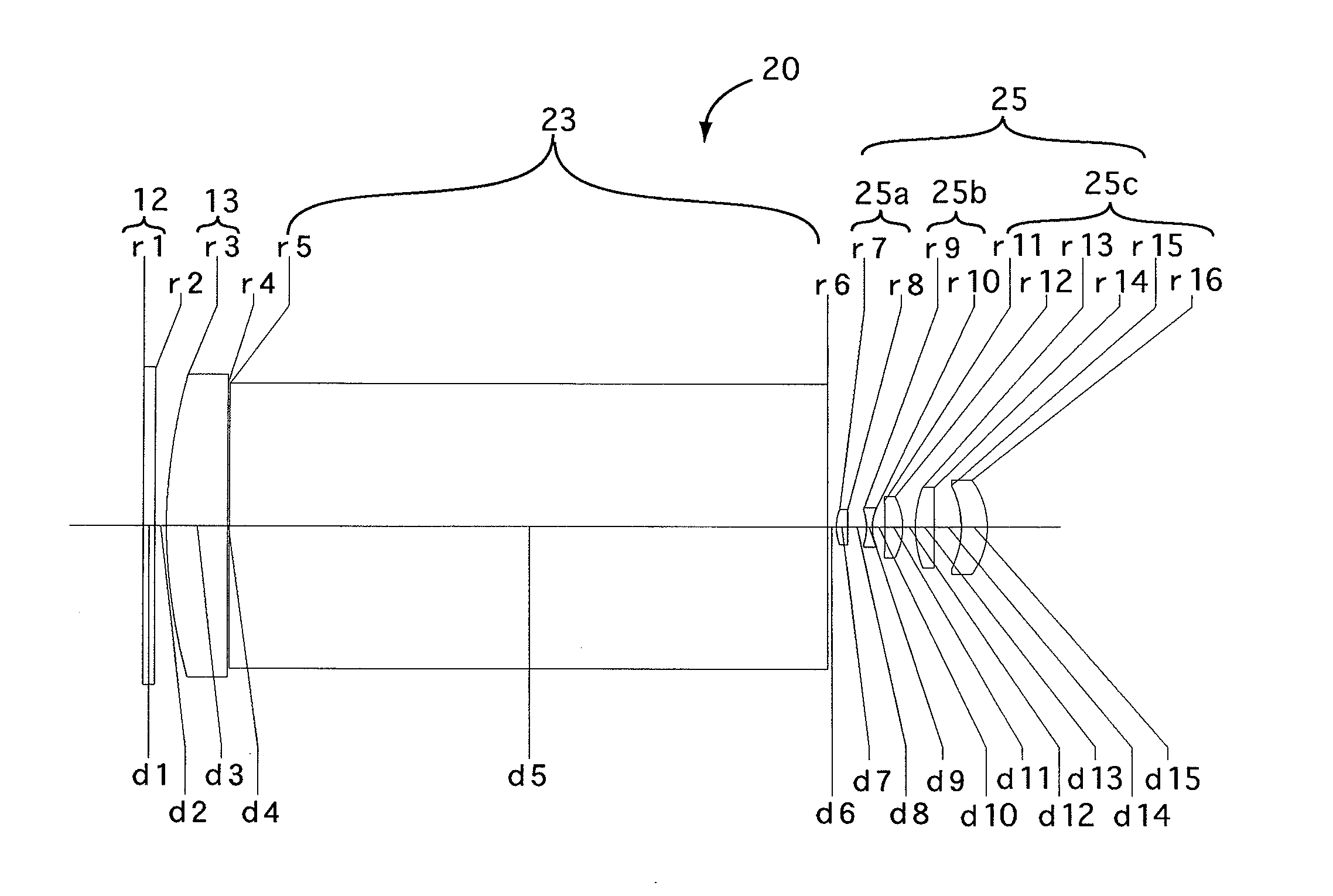
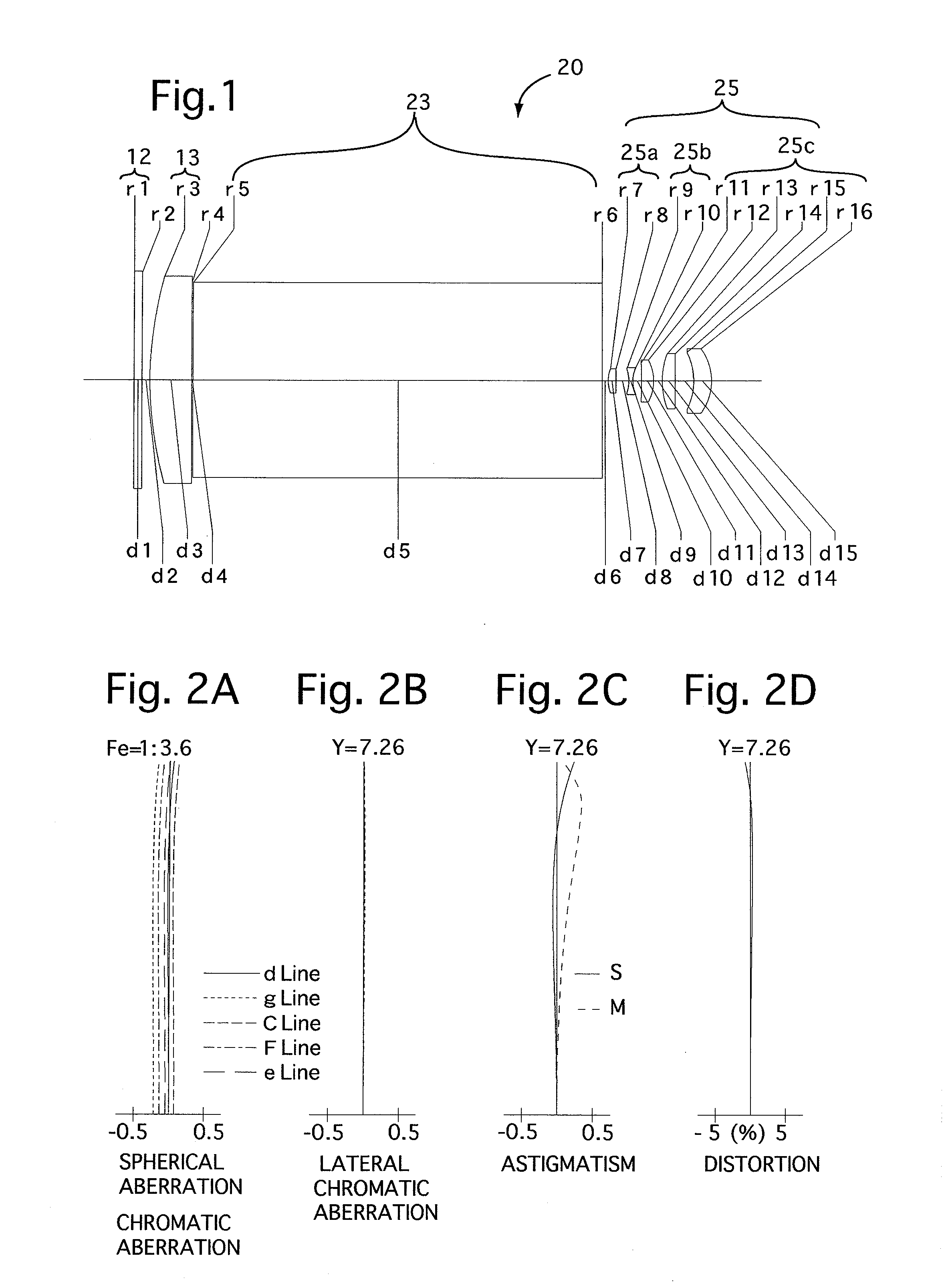
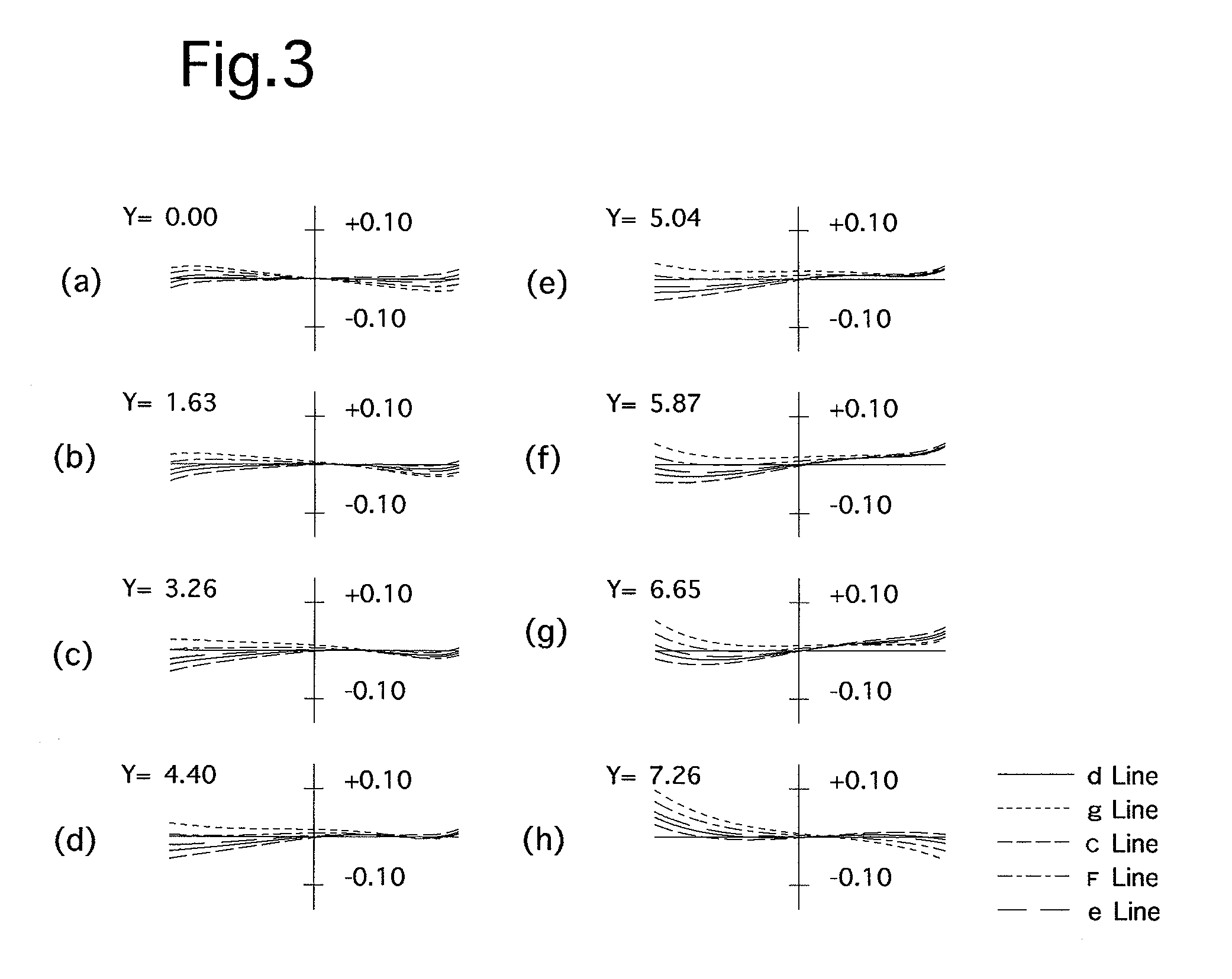
[0080]FIG. 1 is the lens arrangement of the relay finder optical system according to the first embodiment of the present invention. FIGS. 2A through 2D show aberrations occurred in the lens arrangement shown in FIG. 1. FIGS. 3A through 3H show transverse aberrations (coma) occurred in the lens arrangement shown in FIG. 1.

[0081]Table 1 shows the numerical data of the first embodiment.

[0082]Furthermore, surface No. 1 designates the primary imaging plane 12.

TABLE 1Fe = 1:3.6f = 34.25M = −0.27fB = 5.00Surf. No.rdNdν2∞2.00—— 3*90.00010.501.4917657.44∞0.30——5∞102.081.5163364.16∞1.50——78.0641.901.7725049.688898.4163.20——9−9.1001.001.6989530.110 8.4212.14——11 −104.2223.001.7725049.612 −10.8012.17——13 19.6753.201.6935053.214 526.2814.68——15 −15.6114.501.7725049.616 −13.119———The symbol * designates the aspherical surface which is rotationally symmetrical with respect to the optical axis.

[0083]Aspherical surface data (the aspherical surface coefficients not indicated are zero (0.00)):

Surf. No...

embodiment 2

[0084]FIG. 4 is the lens arrangement of the relay finder optical system according to the second embodiment of the present invention. FIGS. 5A through 5D show aberrations occurred in the lens arrangement shown in FIG. 4. FIGS. 6A through 6H show transverse aberrations (coma) occurred in the lens arrangement shown in FIG. 4.

[0085]Table 2 shows the numerical data of the second embodiment.

[0086]Furthermore, surface No. 1 designates the primary imaging plane 12.

TABLE 2Fe = 1:4.0f = 35.39M = −0.31fB = 4.9Surf. No.rdNdν1∞2.001.4917657.42∞2.00—— 3*90.00010.501.4917657.44∞0.30——5∞102.081.5163364.16∞1.50——79.0831.901.7725049.6877.0634.27——9−10.4111.001.6668033.010 9.7982.30——11 −90.6803.001.7725049.612 −12.7430.50——13 14.6374.201.6935053.214 32.8628.03——15 −94.9994.501.7725049.616 −33.424———The symbol * designates the aspherical surface which is rotationally symmetrical with respect to the optical axis.

[0087]Aspherical surface data (the aspherical surface coefficients not indicated are zero (...

embodiment 3

[0088]FIG. 7 is the lens arrangement of the relay finder optical system according to the third embodiment of the present invention. FIGS. 8A through 8D show aberrations occurred in the lens arrangement shown in FIG. 7. FIGS. 9A through 9H show transverse aberrations (coma) occurred in the lens arrangement shown in FIG. 9.

[0089]Table 3 shows the numerical data of the third embodiment.

[0090]Furthermore, surface No. 1 designates the primary imaging plane 12.

TABLE 3Fe = 1:3.2f = 30.48M = −0.25fB = 5.10Surf. No.rdNdν1∞2.0001.4917657.42∞2.000—— 3*90.00010.5001.4917657.44∞0.300——5∞102.0801.5163364.16∞1.500——710.4621.9001.7725049.68−128.3272.580——9−12.3931.0001.6889331.110 11.7522.300——11 −36.5093.0001.7725049.612 −11.9950.500——13 24.3864.2001.7410052.714 −107.3587.490——15 −37.5384.5001.7725049.616 −23.830———The symbol * designates the aspherical surface which is rotationally symmetrical with respect to the optical axis.

[0091]Aspherical surface data (the aspherical surface coefficients not ...


PUM


Abstract

A relay finder optical system, of a single-lens reflex camera, includes a condenser lens group, a prism, and a relay lens group, in this order from a primary imaging plane.
An image, which is formed on the primary imaging plane, and is upside down and inverted from left to right, is re-formed on a secondary imaging plane for viewing by a photographer.
The relay lens group includes a positive front lens group, a negative intermediate lens group, and a positive rear lens group, in this order from the object.
The most photographer's-eye side lens element of the positive rear lens group comprises a positive lens element having a convex surface facing toward the image, and satisfies the following conditions:
1<SF   (1)
−6<f/fM<−3   (2)
SF: the shaping factor of the most photographer's-eye side positive lens element (SF=(r1+r2)/(r1−r2)); r1: the radius of curvature of the object-side surface of the most photographer's-eye side positive lens element; r2: the radius of curvature of the photographer's eye-side surface of the most photographer's-eye side positive lens element; f: the focal length of the relay finder optical system; and fM: the focal length of the negative intermediate lens group.

Description

BACKGROUND OF THE INVENTION[0001]1. Field of the Invention[0002]The present invention relates to a relay finder optical system of a single-lens reflex (SLR) camera.[0003]2. Description of the Prior Art[0004]A finder optical system of an SLR camera has a fundamental structure in which an image formed on a primary imaging plane (focusing plate) through a photographing lens system is re-formed on a secondary imaging plane through a relay finder optical system, and the secondary image is viewed by the photographer through a Lupe (magnifying) optical system (an eyepiece optical system). For example, Japanese Unexamined Patent Publication Nos. 2001-290087 and 2003-121760 can be taken as the prior art.[0005]If an attempt is made to reduce the magnification of the relay finder optical system, the size of the secondary imaging plane can be made smaller with respect to the size of the field-of-view frame. Consequently, such a smaller magnification of the relay finder optical system contribute...

Claims


Application Information

Patent Timeline
Patent Type & Authority Applications(United States)
IPC IPC(8): G03B13/02
CPCG02B23/14G03B13/18G03B13/08G02B25/001
Inventor YANO, TAKAAKI
Owner RICOH IMAGING COMPANY
Why Eureka
Try Eureka