Optical lens, camera module and electronic equipment

A technology of optical lens and camera module, which is applied in optics, optical components, instruments, etc., can solve the problems of increasing the difficulty of optical lens and unfavorable design requirements for miniaturization of optical lens, and achieve shortened total length, large image surface and imaging quality, shortening the effect of correcting aberrations

Pending Publication Date: 2022-02-08
JIANGXI JINGCHAO OPTICAL CO LTD
View PDF0 Cites 0 Cited by
  • Summary
  • Abstract
  • Description
  • Claims
  • Application Information

AI Technical Summary

Problems solved by technology

In related technologies, in order to achieve a large image surface and achieve higher imaging quality, the aberration of the optical lens is corrected by increasing the number of lenses. However, the

Method used


Image

  • Optical lens, camera module and electronic equipment
  • Optical lens, camera module and electronic equipment
  • Optical lens, camera module and electronic equipment

Examples


Embodiment 1

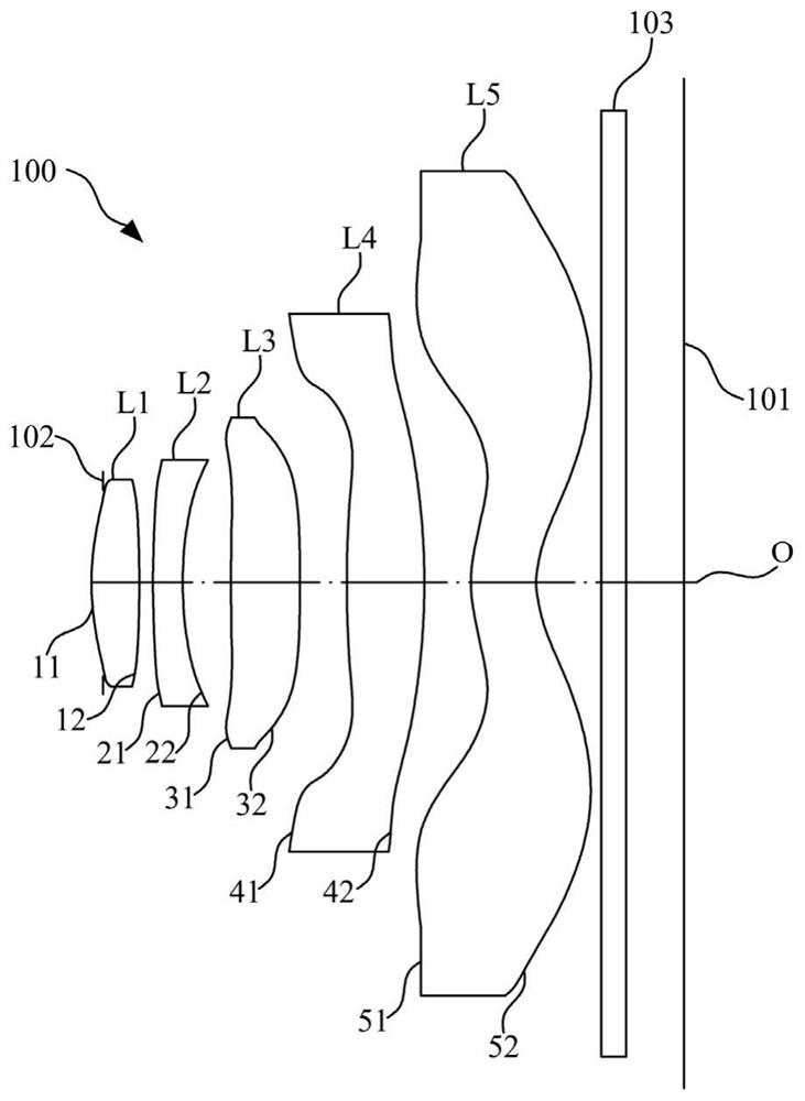
[0070] The structural schematic diagram of the optical lens 100 disclosed in Embodiment 1 of the present invention is as follows figure 1 As shown, the optical lens 100 includes a diaphragm 102, a first lens L1, a second lens L2, a third lens L3, a fourth lens L4, a fifth lens L5 and a filter lens arranged in sequence from the object side to the image side along the optical axis O. Light sheet 103.

[0071] Further, the first lens L1 has positive refractive power, the second lens L2 has negative refractive power, the third lens L3 has positive refractive power, the fourth lens L4 has positive refractive power, and the fifth lens L5 has negative refractive power.

[0072] Further, the object side 11 and image side 12 of the first lens L1 are both convex at the near optical axis O; the object side 21 and image side 22 of the second lens L2 are respectively convex and concave at the near optical axis O; The object side 31 and the image side 32 of the third lens L3 are convex at ...

Embodiment 2

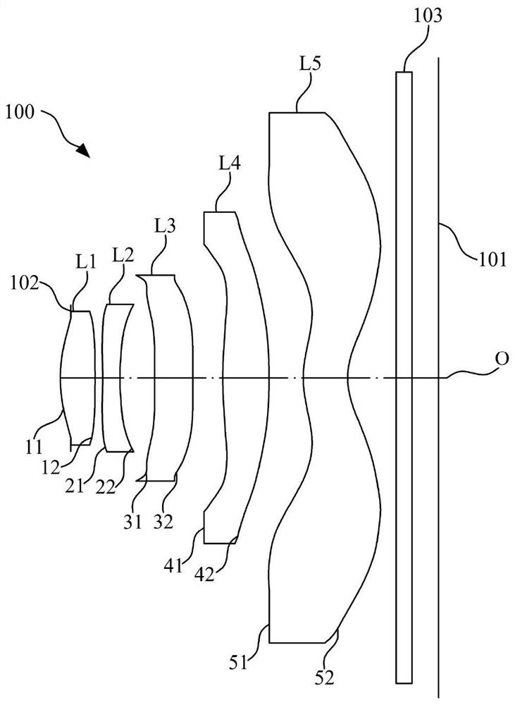
[0086] The structural schematic diagram of the optical lens 100 disclosed in Embodiment 2 of the present invention is as follows image 3 As shown, the optical lens 100 includes a diaphragm 102, a first lens L1, a second lens L2, a third lens L3, a fourth lens L4, a fifth lens L5 and a filter lens arranged in sequence from the object side to the image side along the optical axis O. Light sheet 103.

[0087]Further, the first lens L1 has a positive refractive power, the second lens L2 has a negative refractive power, the third lens L3 has a negative refractive power, the fourth lens L4 has a positive refractive power, and the fifth lens L5 has a negative refractive power .

[0088] Further, the object side 11 and image side 12 of the first lens L1 are both convex at the near optical axis O; the object side 21 and image side 22 of the second lens L2 are both concave at the near optical axis O; the third lens The object side 31 and image side 32 of L3 are respectively concave a...

Embodiment 3

[0098] The structural schematic diagram of the optical lens 100 disclosed in Embodiment 3 of the present invention is as follows Figure 5 As shown, the optical lens 100 includes a diaphragm 102, a first lens L1, a second lens L2, a third lens L3, a fourth lens L4, a fifth lens L5 and a filter lens arranged in sequence from the object side to the image side along the optical axis O. Light sheet 103.

[0099] Further, the first lens L1 has positive refractive power, the second lens L2 has negative refractive power, the third lens L3 has positive refractive power, the fourth lens L4 has positive refractive power, and the fifth lens L5 has negative refractive power.

[0100] Further, the object side 11 and image side 12 of the first lens L1 are respectively convex and concave at the near optical axis O; the object side 21 and image side 22 of the second lens L2 are respectively convex and concave at the near optical axis O The object side 31 and image side 32 of the third lens L...


PUM


Abstract

The invention discloses an optical lens, a camera module and electronic equipment. The optical lens comprises first to fifth lenses from an object side to an image side along an optical axis; the first lens has positive focal power, and the object side surface of the first lens is a convex surface; the second lens has negative focal power, and the image side surface of the second lens is a concave surface; the third lens has focal power; the fourth lens has focal power, and the object side surface of the fourth lens is a convex surface; and the fifth lens has focal power, and the object side surface and the image side surface of the fifth lens are a convex surface and a concave surface. The optical lens further meets the relational expression that TTL/ImgH is larger than 1.1 and smaller than 1.3. According to the optical lens, the camera module and the electronic equipment provided by the embodiment of the invention, the design requirements of miniaturization, large image surface and high imaging quality of the optical lens can be met.

Description

technical field [0001] The invention relates to the technical field of optical imaging, in particular to an optical lens, a camera module and electronic equipment. Background technique [0002] With people's pursuit of thinner and smaller electronic products, the thinner and smaller structural features of optical lenses combined with large image area and high imaging quality shooting effects have gradually become the development trend of optical lenses. In related technologies, in order to achieve a large image surface and achieve higher imaging quality, the aberration of the optical lens is corrected by increasing the number of lenses. However, the increase in the number of lenses not only increases the design and processing of the optical lens. The difficulty is not conducive to the design requirements of the miniaturization of optical lenses. Contents of the invention [0003] The embodiment of the invention discloses an optical lens, a camera module and electronic equ...

Claims


Application Information

Patent Timeline
IPC IPC(8): G02B13/00G02B13/18
CPCG02B13/0015G02B13/0045G03B30/00
Inventor 龙鑫灿李明刘秀曾晗
Owner JIANGXI JINGCHAO OPTICAL CO LTD
Why Eureka
Try Eureka