Virtual Burst-Switching Networks

a virtual network and burst switching technology, applied in data switching networks, store-and-forward switching systems, multiplex communication, etc., can solve the problems of burst loss, burst latency and burst loss, and uncertainty of the fate of burst thus transmitted

Inactive Publication Date: 2008-09-25
RPX CLEARINGHOUSE
View PDF12 Cites 24 Cited by
  • Summary
  • Abstract
  • Description
  • Claims
  • Application Information

AI Technical Summary

Problems solved by technology

Prior-art optical burst switching has two main drawbacks: burst-transfer latency and burst loss.
The main drawback of this technique is the uncertainty of the fate of a burst thus transmitted.
Even if a very long time gap is kept between a burst-transfer request and the data burst itself, the lack of buffers at the core node may result in burst loss and a significant idle time.
Thus, in the closed-loop scheme, the time delay experienced in sending a burst transfer request and receiving an acceptance before sending a burst may be unacceptably high, leading to idle waiting periods and low network utilization in addition to requiring large storage at the edge nodes.
In the open-loop scheme, a burst may arrive at a core node before the optical switch can be configured to switch the burst and the burst may be lost.
Furthermore, the fact that the burst has been lost at the core node remains unknown to the source node for some time and a lost burst would have to be sent again after a predefined interval of time.
This renders closed-loop burst scheduling inappropriate.
The high round-trip delay requires that the source node have sizeable buffer storage.
On the other hand, open-loop burst scheduling, which overcomes the delay problem, can result in substantial burst loss due to unresolved contention at the core nodes.
Providing high-capacity wide-coverage time-shared networks using bufferless core nodes presents a significant challenge due to the difficulty of time-alignment at the bufferless core nodes.

Method used


Image

  • Virtual Burst-Switching Networks
  • Virtual Burst-Switching Networks
  • Virtual Burst-Switching Networks

Examples


Embodiment Construction

[0061]The terminology used in describing the embodiments of the invention is listed below.

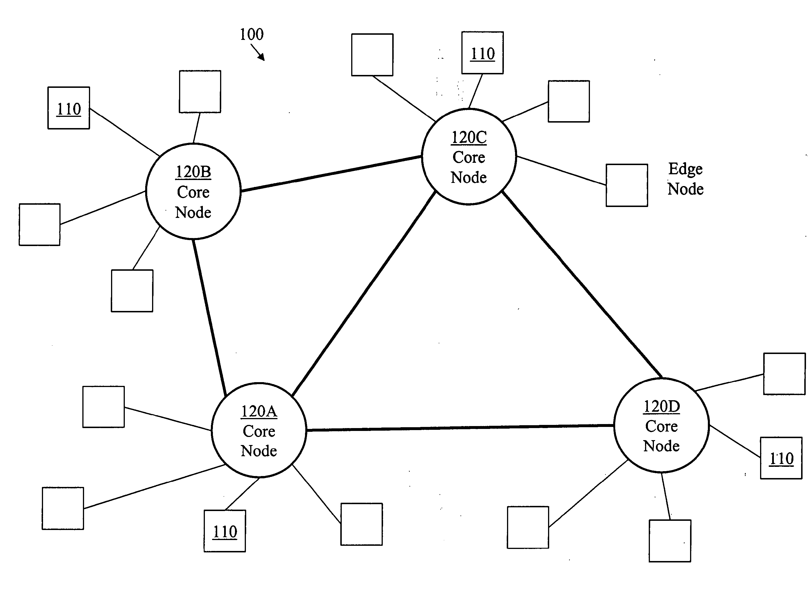
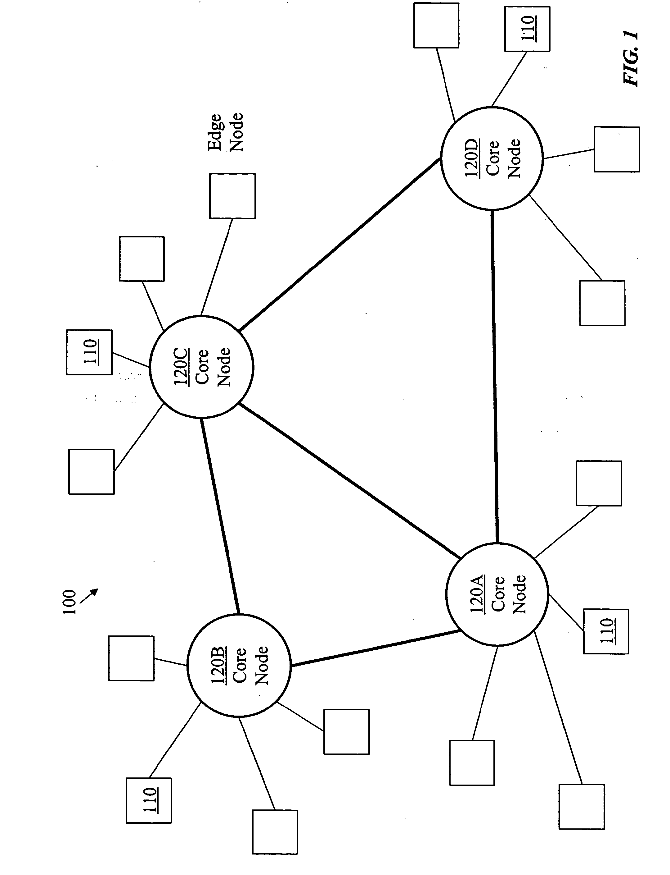
Edge node: A switching node having subtending information sources and sinks and connecting to other nodes is called an edge node.

Source node: An edge node transmitting signals, received from subtending sources, to other nodes is called a source edge node or a source node.

Sink node: An edge node receiving signals from other nodes, for delivery to subtending sinks, is called a sink edge node or a sink node.

Core node: A switching node connecting only to other switching nodes, which may be edge nodes or core nodes, is called a core node.

Input port: A port of a switching node receiving information signals from either a subtending information source or from an external node is called an input port.

Output port: A port of a switching node transmitting information signals to either a subtending information sink or an external node is called an output port.

Outer port: An edge-node port receiving signals ...


PUM


Abstract

A time-shared network comprising edge nodes and optical core nodes may be dynamically divided into several embedded networks, each of which covering selected edge nodes. At least one of the edge nodes may host an embedded-network controller operable to form multiple-source flow-rate allocation requests each of the requests specifying flow-rate allocations to a plurality of paths from several source nodes to several sink nodes. A core node may also host an embedded-network controller or several embedded-network controllers. The time-shared network may use both time-division multiplexing and burst switching.

Description

CROSS-REFERENCE TO RELATED APPLICATIONS[0001]The application is a Divisional of U.S. patent application Ser. No. 10 / 682,467, entitled VIRTUAL BURST SWITCHING NETWORKS, filed Oct. 9, 2003, which is incorporated by reference.FIELD OF THE INVENTION[0002]The present invention relates to a data network and, in particular, to an agile burst-switching network that includes a multiplicity of embedded virtual burst-switching networks.BACKGROUND[0003]Prior-art optical burst switching has two main drawbacks: burst-transfer latency and burst loss. In a closed-loop scheme, a source node sends a request to a core node for transferring a burst, the request including a destination and size of the burst, and waits for a message from the core node, where the message acknowledges that the optical switch in the core node is properly configured, before sending the burst. In an open-loop scheme, the burst follows the burst transfer request after a predetermined time period, presumably sufficient to sched...

Claims


Application Information

Patent Timeline
Patent Type & Authority Applications(United States)
IPC IPC(8): H04J14/08
CPCH04L12/56H04L45/122H04L45/124H04L45/20H04Q2011/0064H04L45/40H04L45/62H04Q11/0066H04Q2011/0045H04L45/302
Inventor BESHAI, MAGED E.JAMOUSSI, BILEL N.
Owner RPX CLEARINGHOUSE
Why Eureka
Try Eureka