

Indirect bonding trays for orthodontic treatment and methods for making the same
- Summary
- Abstract
- Description
- Claims
- Application Information
AI Technical Summary
Benefits of technology
Problems solved by technology
Method used
Image

Examples
example
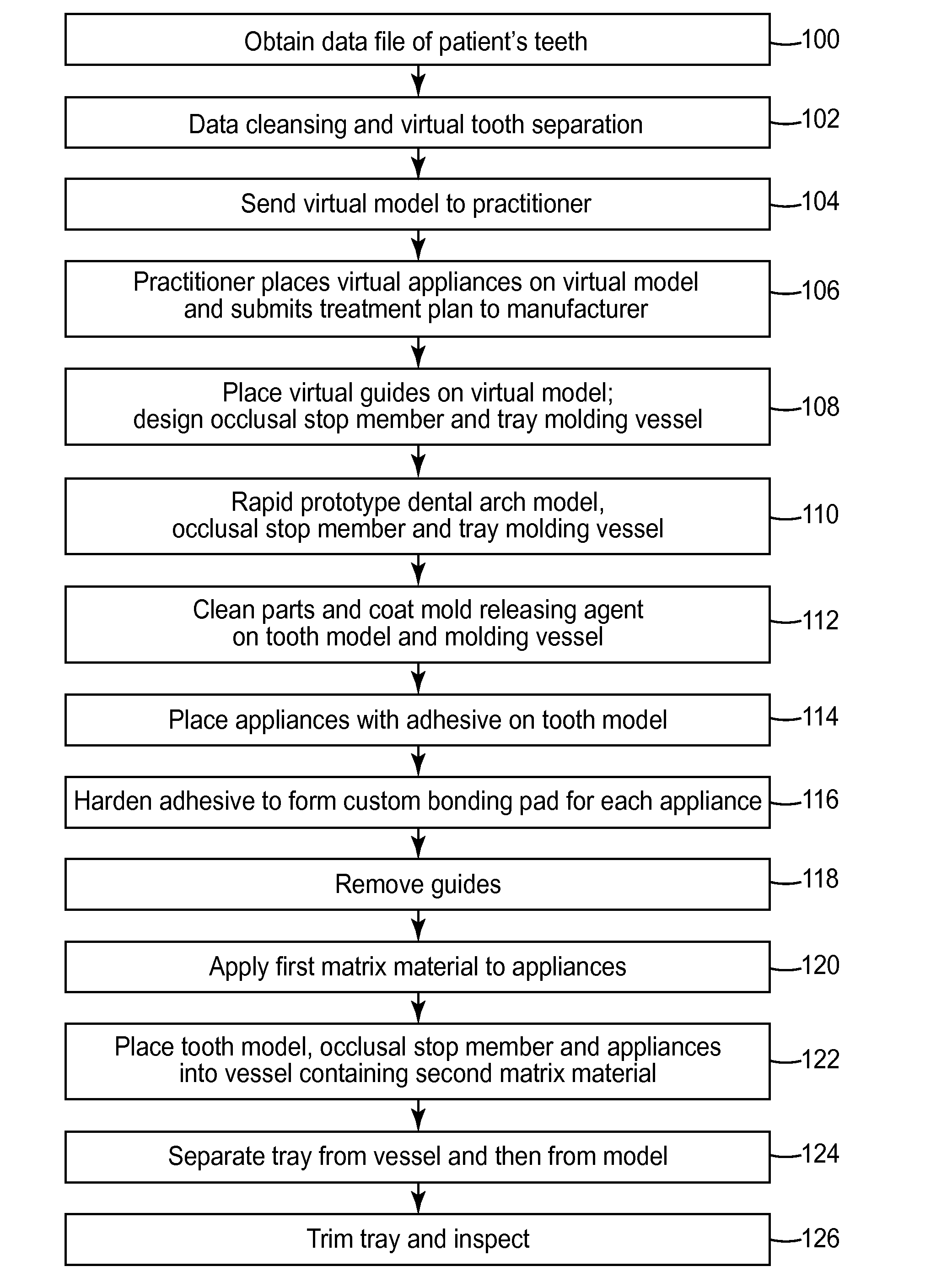
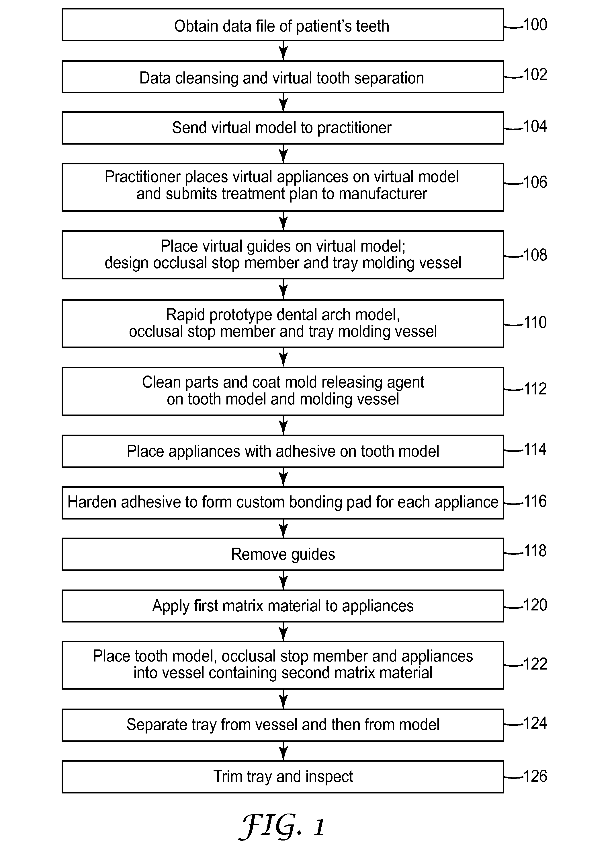
[0137]Experiments were conducted to compare the transfer accuracy (i.e., the accuracy of appliance placement) of the bonding trays of the present invention with bonding trays of other constructions. Three digital data files, representing the shape of three different dental arches, were obtained. Each of the three data files was used to make a bonding tray and molding vessel according to the methods described above in connection with bonding tray 88 and molding vessel 76, but using an occlusal stop member similar to the occlusal stop member 70′ illustrated in FIG. 18. To make these three trays, the first matrix material was the Emiluma brand silicone material and the second matrix material was the Memosil 2 brand vinyl polysiloxane material as mentioned above, and sufficient first matrix material was applied to the bracket appliances to generally appear as shown in FIG. 13. The occlusal stop member and tray molding vessel were made using the FullCure 720 printing material.
[0138]For p...
PUM
 Abstract
Description
Claims
Application Information