Method and Apparatus for Handling Random Access Procedure in a Wireless Communications System

a random access and wireless communication technology, applied in the direction of automatic exchange, telephonic communication, electric devices, etc., can solve the problems of timing offset, inability to determine, and problems that may occur, and achieve accurate handling, accurate handling, and accurate handling

a random access and wireless communication technology, applied in the direction of automatic exchange, telephonic communication, electric devices, etc., can solve the problems of timing offset, inability to determine, and problems that may occur, and achieve accurate handling, accurate handling, and accurate handling

US20080233941A1Active Publication Date: 2008-09-25INNOVATIVE SONIC

Image

  • Method and Apparatus for Handling Random Access Procedure in a Wireless Communications System
  • Method and Apparatus for Handling Random Access Procedure in a Wireless Communications System
  • Method and Apparatus for Handling Random Access Procedure in a Wireless Communications System

Examples


Embodiment Construction

[0052]Please refer to FIG. 12, which illustrates a schematic diagram of a wireless communications system 1200. The wireless communications system 1200 is preferably an LTE system, and is briefly composed of a network and a plurality of UEs. In FIG. 12, the network and the UEs are simply utilized for illustrating the structure of the wireless communications system 1200. Practically, the network terminal may comprise a plurality of base stations (or Node B), radio network controllers and so on according to actual demands, and the UEs can be devices such as mobile phones, computer systems, etc.

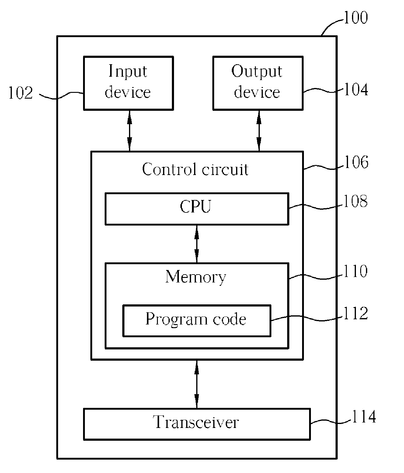
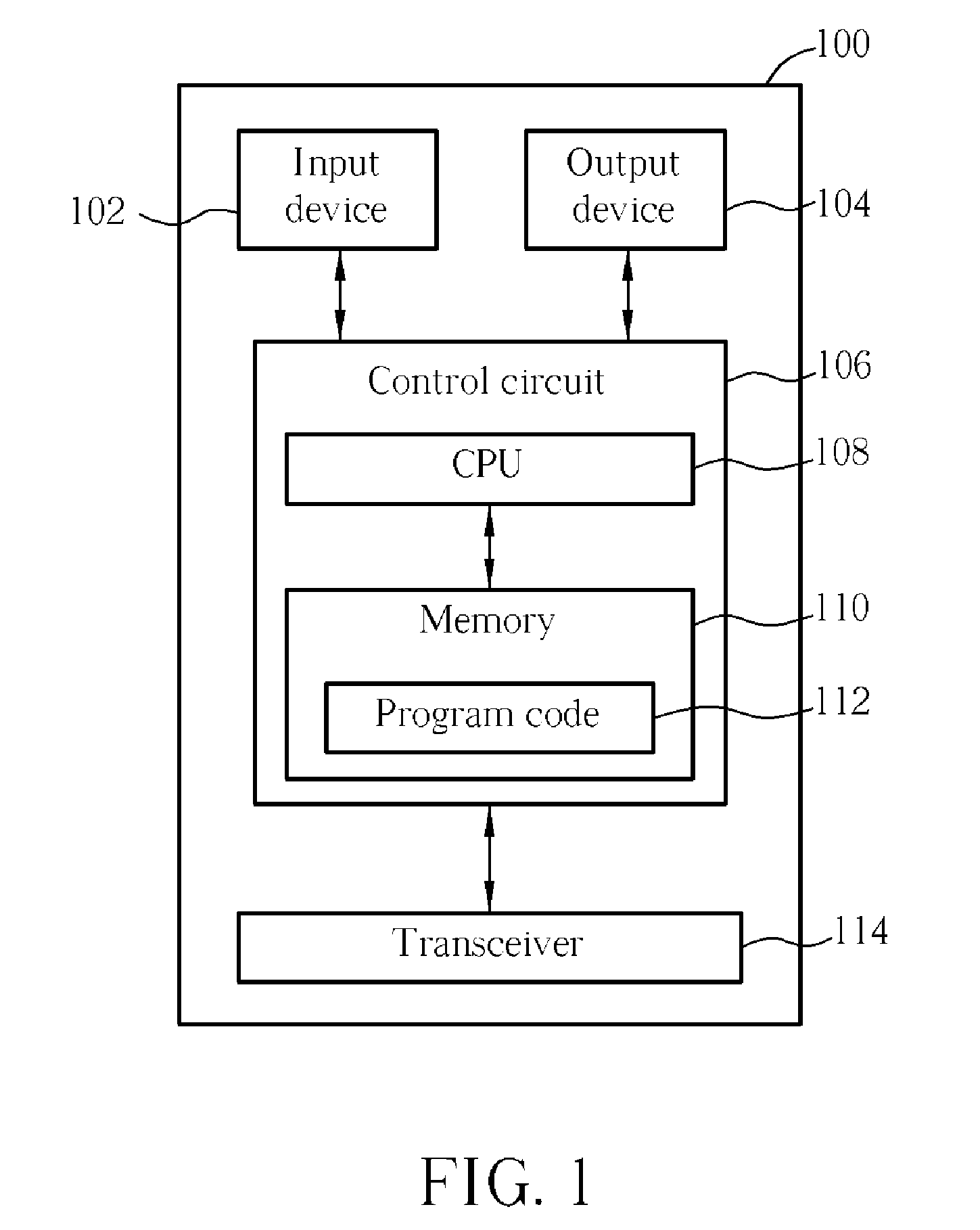
[0053]Please refer to FIG. 1, which is a functional block diagram of a communications device 100. The communications device 100 can be used for implementing the network and the UE shown in FIG. 12. For the sake of brevity, FIG. 1 only shows an input device 102, an output device 104, a control circuit 106, a central processing unit (CPU) 108, a memory 110, a program code 112, and a transceiver 114...


PUM


Abstract

A method for handling a random access procedure in a user equipment, called UE hereinafter, of a wireless communications system includes outputting a message 3 as a scheduled transmission not including a specific field indicating whether the UE has a cell Radio Network Temporary Identifier, called C-RNTI hereinafter, or not during the random access procedure.

Description

CROSS REFERENCE TO RELATED APPLICATIONS[0001]This application claims the benefit of U.S. Provisional Application No. 60 / 895,987, filed on Mar. 3, 2007 and entitled “Method and Apparatus to improve LTE Random access procedure”, the benefit of U.S. Provisional Application No. 60 / 945,948, filed on Jun. 25, 2007 and entitled “Method and Apparatus to optimize Random Access Procedure”, and the benefit of U.S. Provisional Application No. 60 / 983,218, filed on Oct. 28, 2007 and entitled “Method and Apparatus to improve Random Access Procedure and related HARQ operation”, the contents of which are incorporated herein by reference.BACKGROUND OF THE INVENTION[0002]1. Field of the Invention[0003]The present invention relates to a method and apparatus for handling random access procedure in a wireless communications system, and more particularly, to a method and apparatus for implementing timing alignment and resource request, so as to enhance system efficiency.[0004]2. Description of the Prior A...

Claims


Application Information

Patent Timeline
25 Sep 2008
Publication
US20080233941A1
IPC
H04M3/00; H04W74/08
CPC
H04W74/0833; H04W74/002; H04W74/0838; H04W74/006
Inventors
JEN, YU-CHIH