Laryngoscope blade

Inactive Publication Date: 2008-09-25
VITAL SIGNS INC
View PDF23 Cites 20 Cited by
  • Summary
  • Abstract
  • Description
  • Claims
  • Application Information

AI Technical Summary

Problems solved by technology

These component parts, particularly the poppets including the balls and springs, requir

Method used


Image

  • Laryngoscope blade
  • Laryngoscope blade
  • Laryngoscope blade

Examples


Embodiment Construction

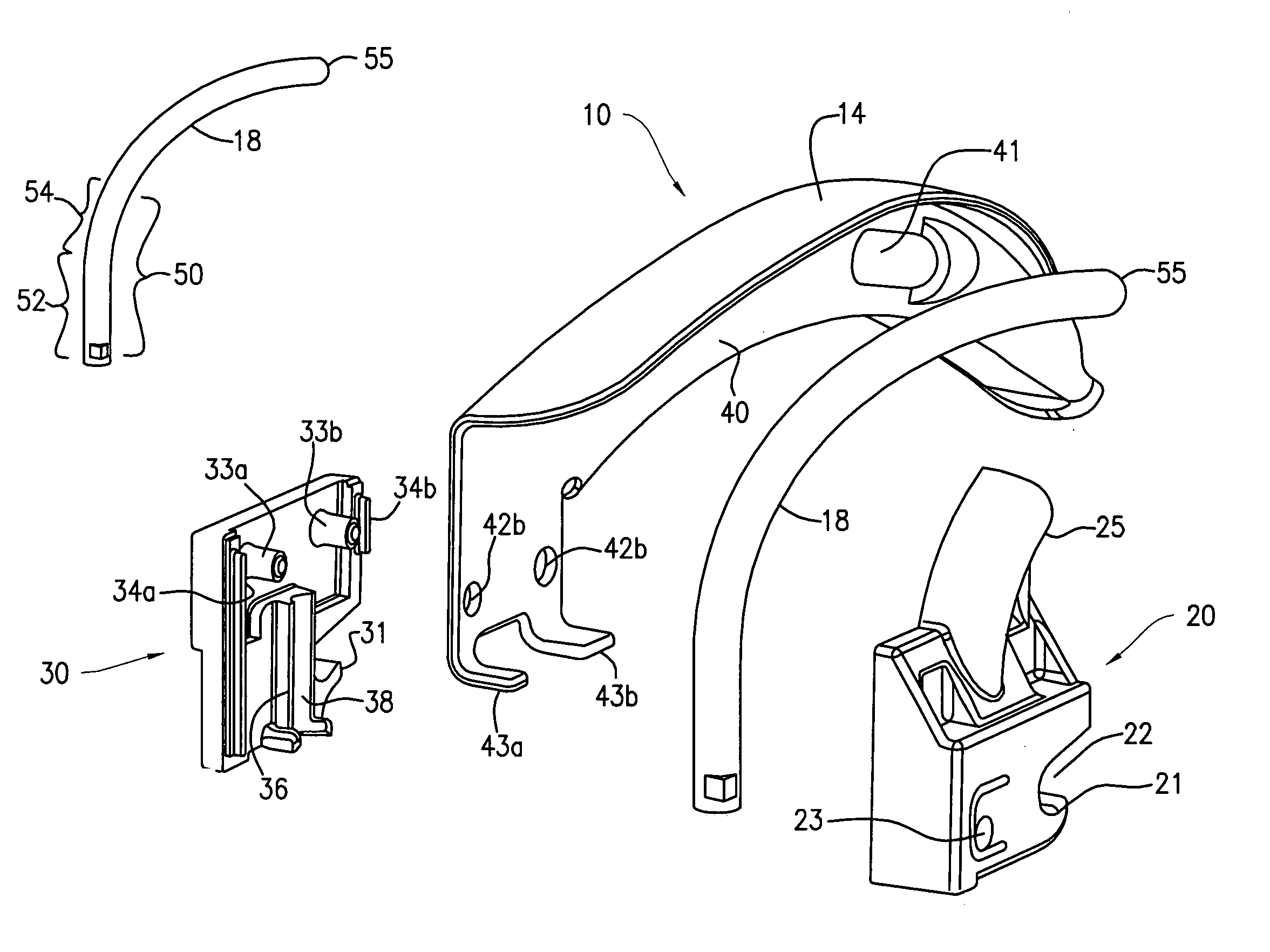
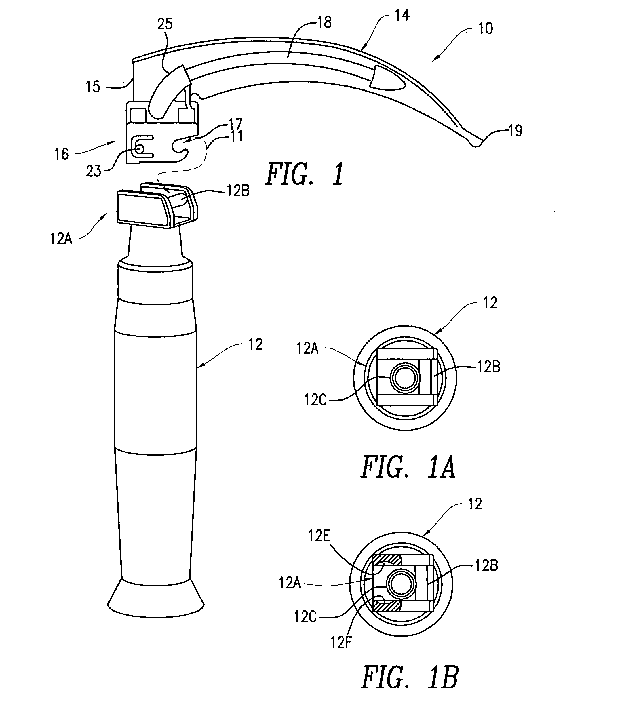
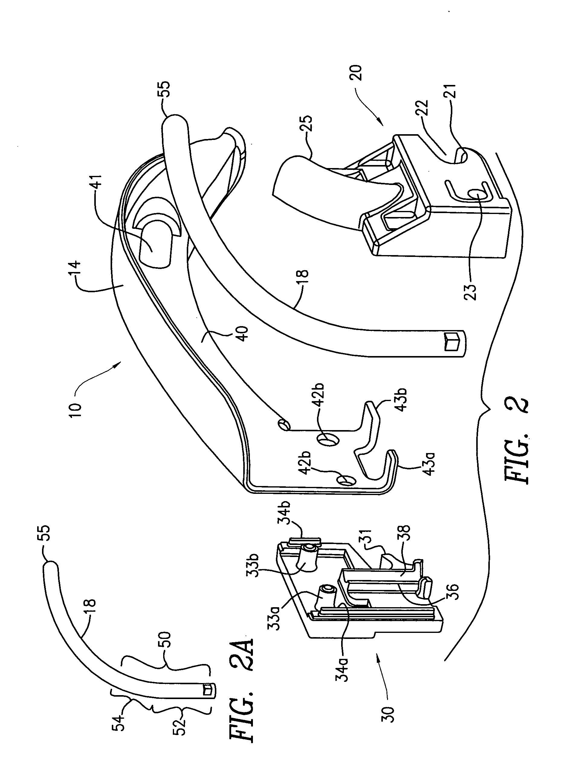
[0031]An embodiment of the laryngoscope blade of the present invention is shown in FIG. 1 and indicated by general numerical designation 10, and as indicated by the irregular line 11, is for being mounted removably to the laryngoscope handle indicated by general numerical designation 12 in FIG. 1. The laryngoscope blade 10 includes a blade portion indicated by general numerical designation 14, a base portion indicted by general numerical designation 16 and an optic light pipe 18. The laryngoscope handle 12 may be any suitable laryngoscope handle known to the art and may be, for example, a laryngoscope handle of the type commonly referred to as Fiber Illuminated System or Green System Handles and, by way of further example, may be the laryngoscope handle available from Vital Signs, Inc., 20 Campus Road, Totowa, N.J., and sold under the trademark Greenlight II. Solely for purposes of illustration of the use of the laryngoscope blade 10 of the present invention, it will be assumed that...


PUM


Abstract

A laryngoscope blade comprising a blade portion, a base portion and an optic light pipe, the blade portion including a proximal end and a distal end provided with an optic window, the base portion including two base halves mounted to each other and to the proximal end of the blade portion, one of the base halves providing a resilient cantilever latch pin and the other of the base halves providing a rigid hook, the light pipe including a proximal end mounted between the two base halves and a distal end extending through the optic window.

Description

BACKGROUND OF THE INVENTION[0001]This invention relates generally to a laryngoscope blade and more particularly relates to a disposable laryngoscope blade particularly useful with laryngoscope handles commonly referred to as Fiber Illuminated System or Green System Handles. More particularly, this invention relates to a disposable laryngoscope blade of a reduced number of component parts with attendant reduced assembly and manufacturing costs.[0002]Laryngoscope blades are known to the art for examining and visualizing a patient's upper airway and for aiding in placement of an endotracheal tube during intubations. For example, an endotracheal tube is inserted into a patient's trachea to supply oxygen to the patient during a surgical procedure. Generally, a patient's trachea, or wind pipe, is covered by the tongue and the epiglottis which is attached to the base of the tongue at the back of the patient's mouth. For access to the trachea and insertion of the endotracheal tube, the tong...

Claims


Application Information

Patent Timeline
IPC IPC(8): A61B1/267
CPCA61B1/07A61B1/00101A61B1/00105A61B1/267
Inventor GEIST, LEROY D.JUTTE, LEROY D.
Owner VITAL SIGNS INC
Why Eureka
Try Eureka