Toothed trencher track and elements therefor

Inactive Publication Date: 2008-10-02
LATHAM WINCHESTER E
View PDF14 Cites 7 Cited by
  • Summary
  • Abstract
  • Description
  • Claims
  • Application Information

AI Technical Summary

Benefits of technology

[0012]In another aspect, a wear plate can have a smooth planar outer surface permitting the attachment socket for receiving a tooth or other cutting element at any location on the wear plate outer surface. The inner surface of the wear plate includes a pattern

Problems solved by technology

However, in some equipment, the bolts securing the plates to the chain prohibit the use of some locations for sockets to receive the cutting teeth.
Consequently, the sockets are often situated in undesirable locations forward and rearward of the midline of each supporting plate, and twisted or angled in an attempt to locate the tooth points at the desired location.
The forward and rearward displacement of the cutting teeth on each plate causes an unintended change

Method used


Image

  • Toothed trencher track and elements therefor
  • Toothed trencher track and elements therefor
  • Toothed trencher track and elements therefor

Examples


Example

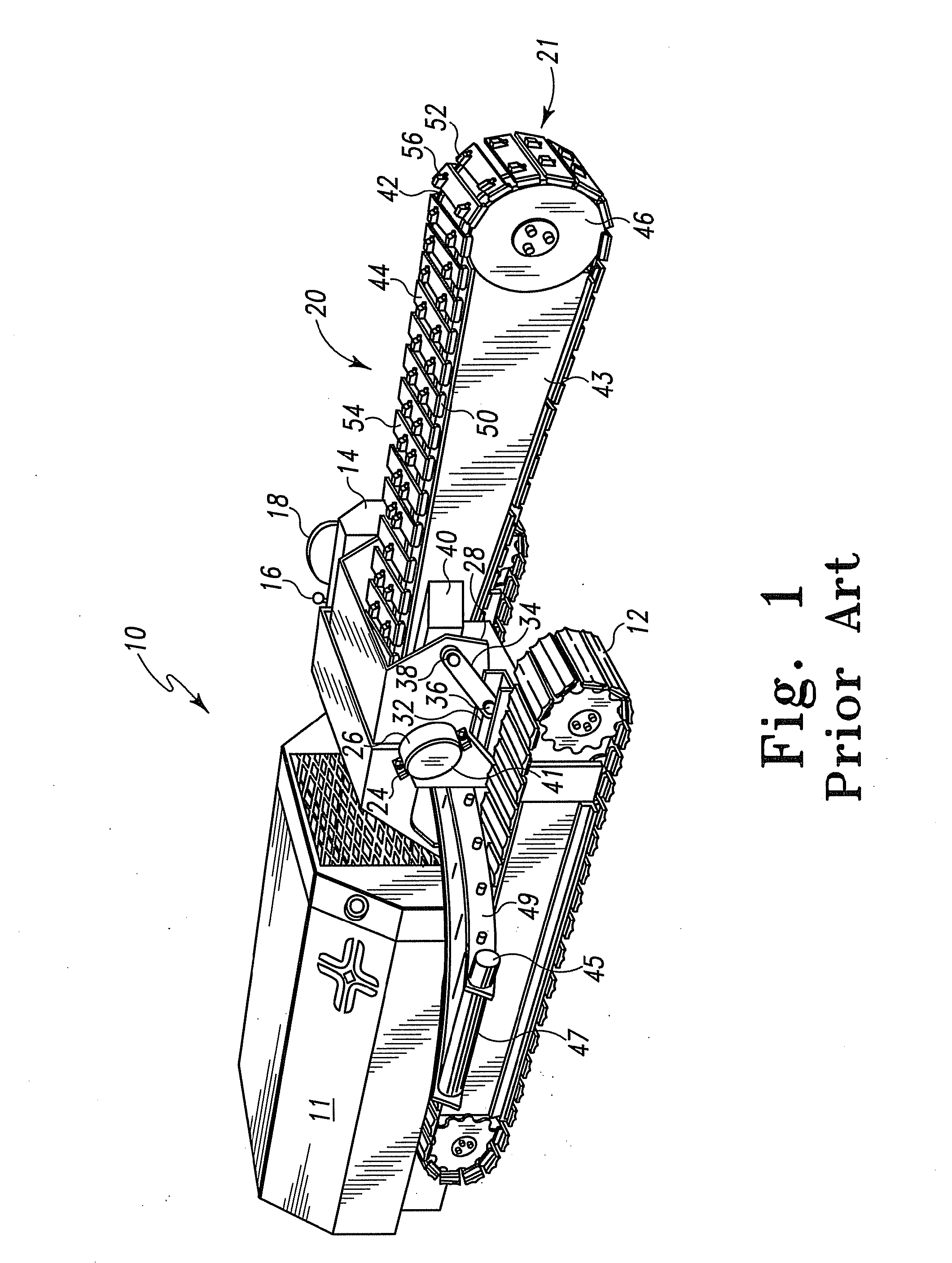
[0030]A typical prior art trencher traction unit 10 shown in FIG. 1 includes a power source 11 that is coupled to tracks 12 for forward and rearward motion of the traction unit 10 under the power provided by the power source. A console 14 can be provided with controls 16 so that an operator can operate the unit 10 from chair 18. The traction unit 10 has an elongate boom assembly 20 having an inner end pivotally mounted to the traction unit 10 on a shaft that is journaled to the traction unit 10 by flanges 24 and 26 on the traction unit 10 and the hood 28. The boom assembly 20 has an outer end 21 that can be raised or lowered under the influence of hydraulic cylinders having one end secured to the traction unit 10, and having a connecting rod 32 pivotally mounted to arm 34 on axle 36. The arm 34 can be pivotally mounted to the cross-bar 38, which passes through the hood 28 and boom assembly 20 so that the hood 28 can be raised and lowered simultaneously with the changes of elevation ...


PUM

PropertyMeasurementUnit
Angleaaaaaaaaaa
Angleaaaaaaaaaa
Angleaaaaaaaaaa

Abstract

An endless chain for cutting and removing spoil from a trench includes a plurality of links pivotally coupled together. A plurality of flight plates are secured to the plurality of links. A pattern of openings extends through each flight plate between the under surface and the outer surface. A plurality of wear plates is positioned over the outer surface of the plurality of flight plates. A plurality of fasteners pass from the under surface of the flight plate through at least some of the pattern of openings in the flight plate and into the wear plate to secure the wear plate to the flight plate. The fasteners securing the wear plates to the flight plates can have outer ends that terminate short of the outer surface of the wear plates in openings in the under surface of the wear plate. Sockets, which include bores receiving cutting elements, can be fixed to the wear plates with a bottom surface of the socket either angled with respect to or flush with the wear plate outer surface.

Description

CROSS-REFERENCE TO RELATED APPLICATIONS[0001]This application is related to and claims all available benefits from U.S. Provisional Application Ser. No. 60 / 920,948 filed Mar. 30, 2007, and U.S. Provisional Application Ser. No. 60 / 978,879 filed Oct. 10, 2007.BACKGROUND[0002]1. Field of the Invention[0003]This invention generally relates to apparatus for digging ditches and trenches. This invention particularly relates to apparatus having a continuous chain to which excavating elements are secured, the chain and excavating elements being suitable for removing hard soils and rock to form a ditch or trench. This invention more particularly relates to track elements secured to a continuous chain that permit a more desirable distribution of cutting or mining teeth that will provide for superior performance of a trencher using such track elements.[0004]2. Background of the Invention[0005]A commonly used type of chain ditcher is characterized by an elongated boom mounted on a supporting str...

Claims


Application Information

Patent Timeline
IPC IPC(8): E02F3/10E02F3/12
CPCB28D1/188E02F3/142E02F3/143E02F9/2866
Inventor LATHAM, WINCHESTER E.
Owner LATHAM WINCHESTER E
Why Eureka
Try Eureka