Adjustable stroke gripper
- Summary
- Abstract
- Description
- Claims
- Application Information
AI Technical Summary
Benefits of technology
Problems solved by technology
Method used
Image

Examples
Embodiment Construction
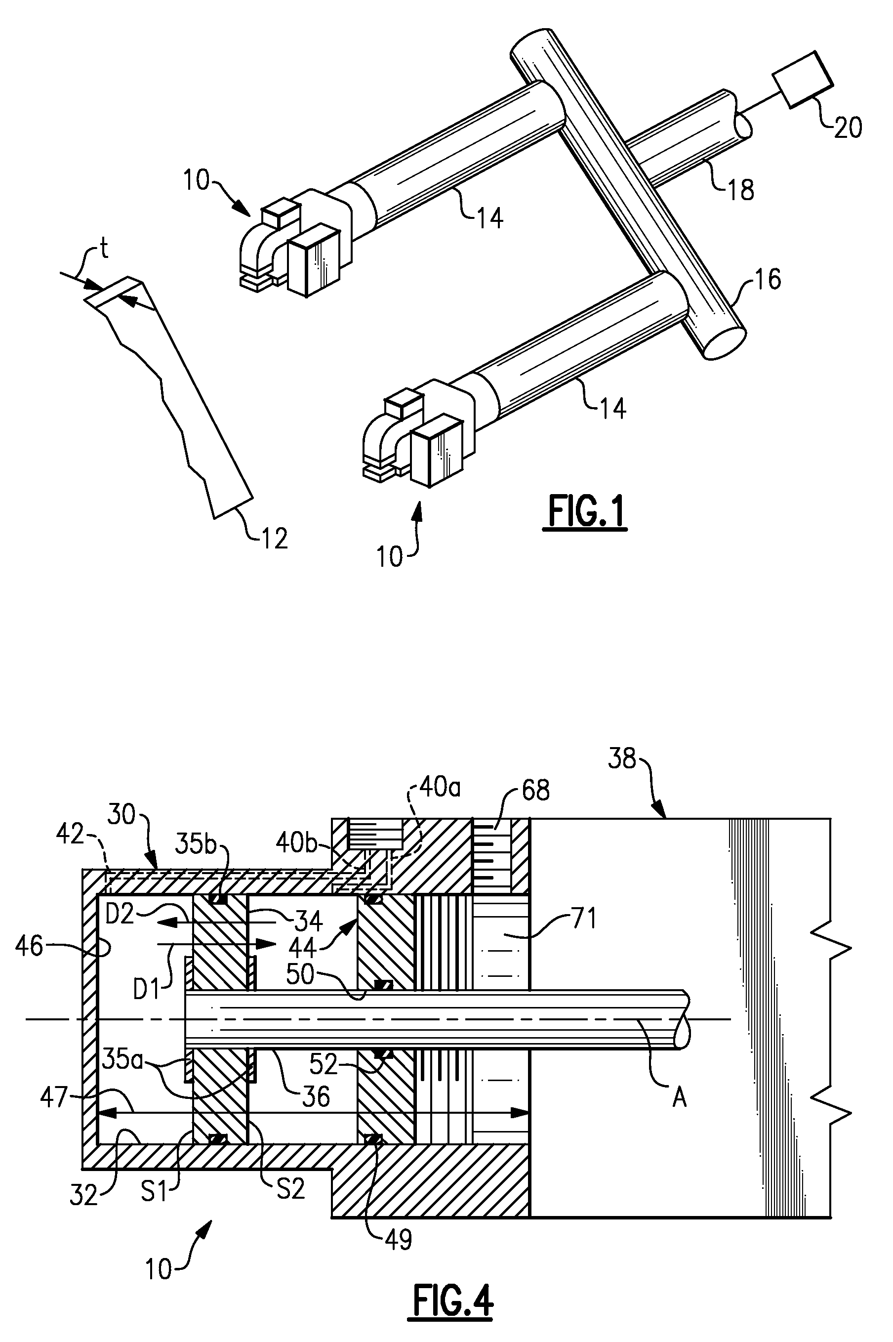
[0014]FIG. 1 illustrates selected portions of several gripper assemblies 10 used in an example industrial setting to grip and move a work piece 12 (shown schematically). The gripper assemblies 10 may be used in a variety of different configurations from that shown. In this example, the gripper assemblies 10 are coupled to extended arms 14, which are each secured to a rail 16. An adapter arm 18 is secured to the rail 16. An automated machine 20, such as a robot, moves the adapter arm 18, the extended arms 14, and the gripper assemblies 10 to desired positions to retrieve and deposit the work pieces 12, such as between work stations.
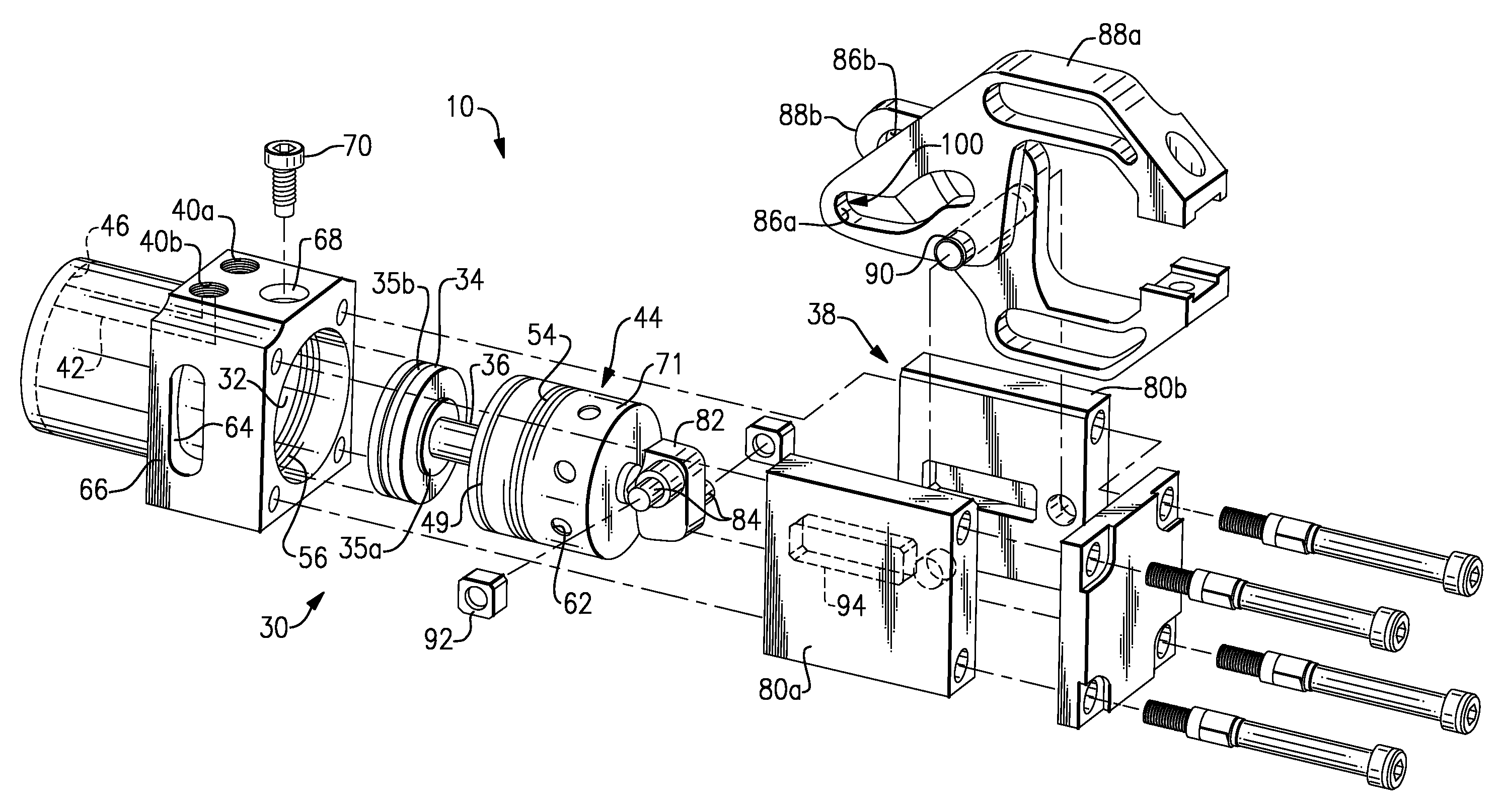
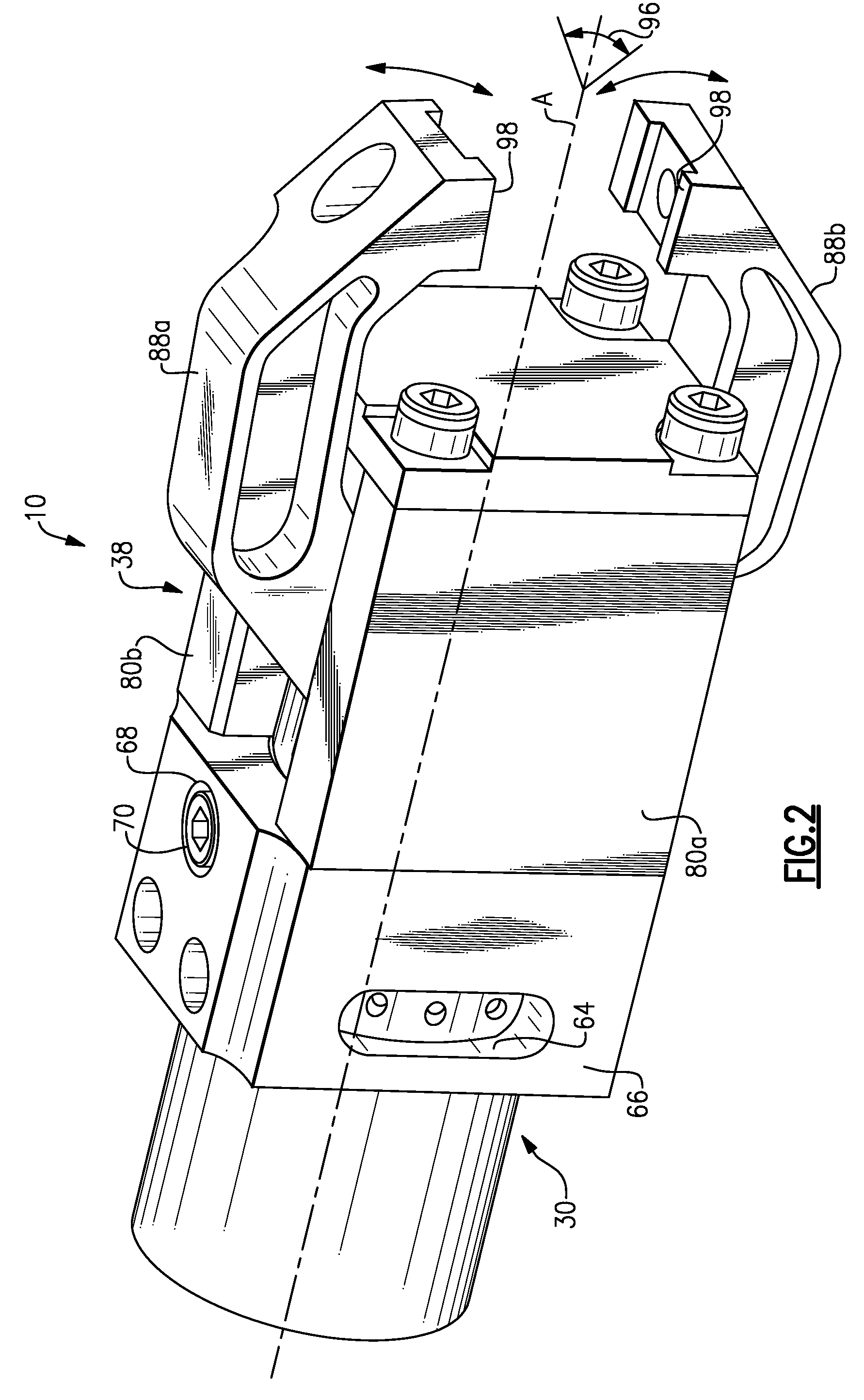
[0015]FIG. 2 shows an example of one of the gripper assemblies 10. FIG. 3 illustrates an exploded view of the gripper assembly 10, and FIG. 4 illustrates a cross-section through a portion of the gripper assembly 10. With reference to these figures, the example gripper assembly 10 includes an actuator 30, such as a pneumatic or hydraulic actuator. It is to ...
PUM
 Abstract
Description
Claims
Application Information
 - Generate Ideas
- Intellectual Property
- Life Sciences
- Materials
- Tech Scout
- Unparalleled Data Quality
- Higher Quality Content
- 60% Fewer Hallucinations
Browse by: Latest US Patents, China's latest patents, Technical Efficacy Thesaurus, Application Domain, Technology Topic, Popular Technical Reports.
© 2025 PatSnap. All rights reserved.Legal|Privacy policy|Modern Slavery Act Transparency Statement|Sitemap|About US| Contact US: help@patsnap.com