Switch gear cell and converter circuit for switching a multiplicity of voltage levels with a switchgear cell such as this

Inactive Publication Date: 2008-10-02
ABB RES LTD
View PDF10 Cites 12 Cited by
  • Summary
  • Abstract
  • Description
  • Claims
  • Application Information

AI Technical Summary

Benefits of technology

[0005]Exemplary embodiments disclosed herein are directed to a switchgear cell which stores as little electrical energy as possible during its operation and can be designed in a space-saving manner. Additional exemplary embodiments disclosed herein are directed to a converte

Problems solved by technology

However, this involves capacitors with a large physical size, which are correspondingly expensive.
Furthermore, the switchgear cell and therefore the converter circuit as well use a large amount of space because of the physically large capacitors, so that a space-saving design, as is desired for many applications, for example for traction applications, is inhibited.
Furthermore, expensive and complex power semiconductor switches are used which have a high withstand voltage.
In addition, the us

Method used


Image

  • Switch gear cell and converter circuit for switching a multiplicity of voltage levels with a switchgear cell such as this
  • Switch gear cell and converter circuit for switching a multiplicity of voltage levels with a switchgear cell such as this
  • Switch gear cell and converter circuit for switching a multiplicity of voltage levels with a switchgear cell such as this

Examples


Example

[0013]The reference symbols used in the drawing and their meanings are listed, in a summarized form, in the list of reference symbols. In principle, identical parts are provided with the same reference symbols in the figures. The described embodiments represent examples of the subject matter of the invention, and have no restrictive effect.

DETAILED DESCRIPTION

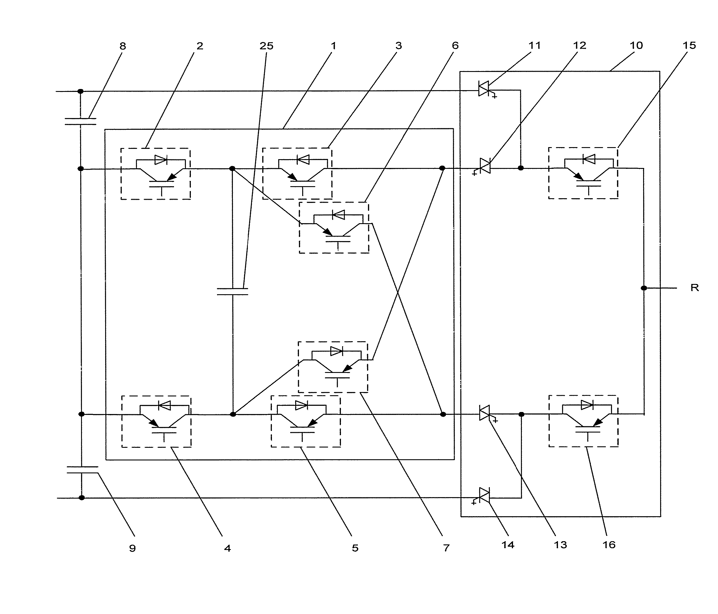
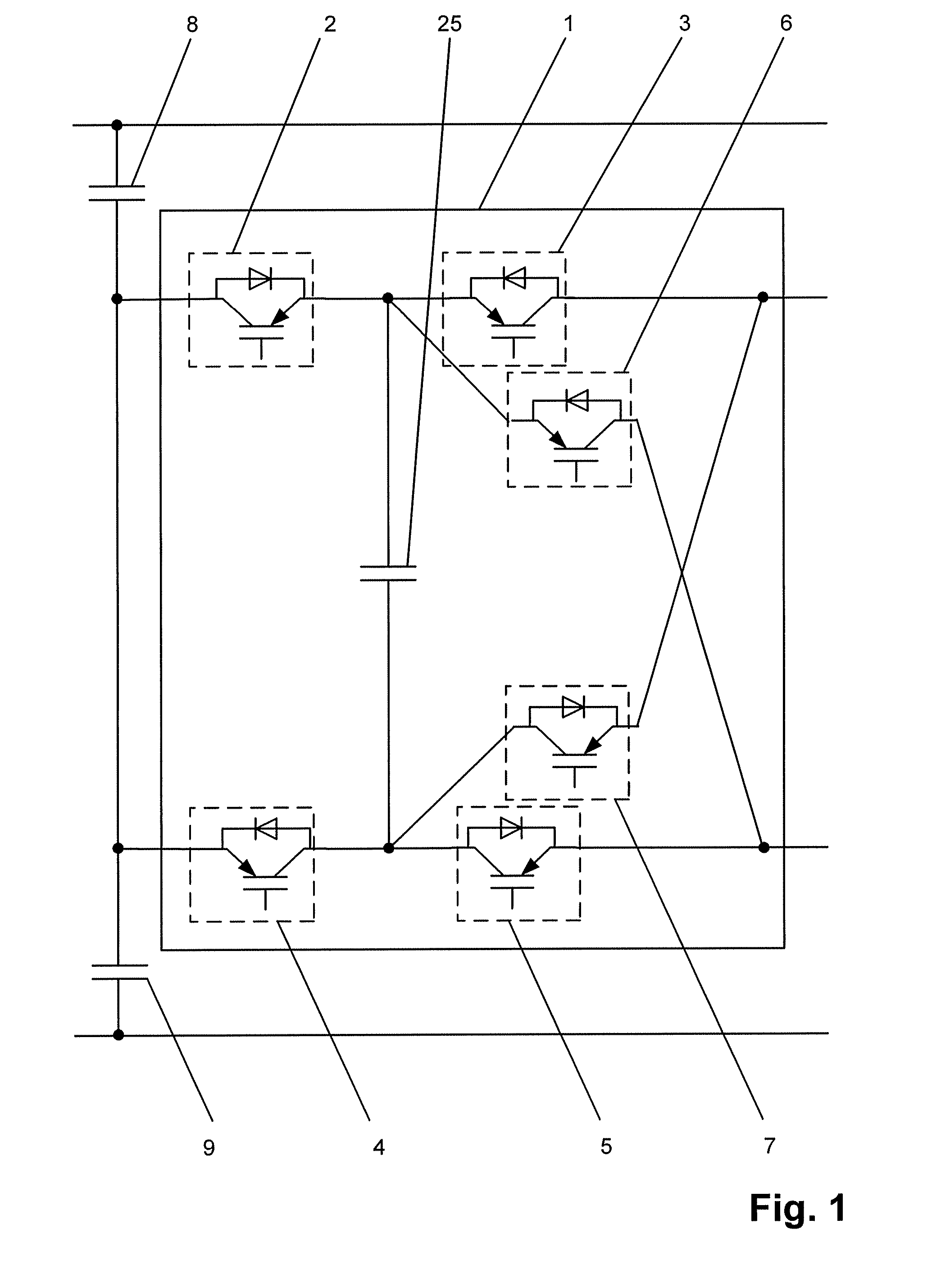
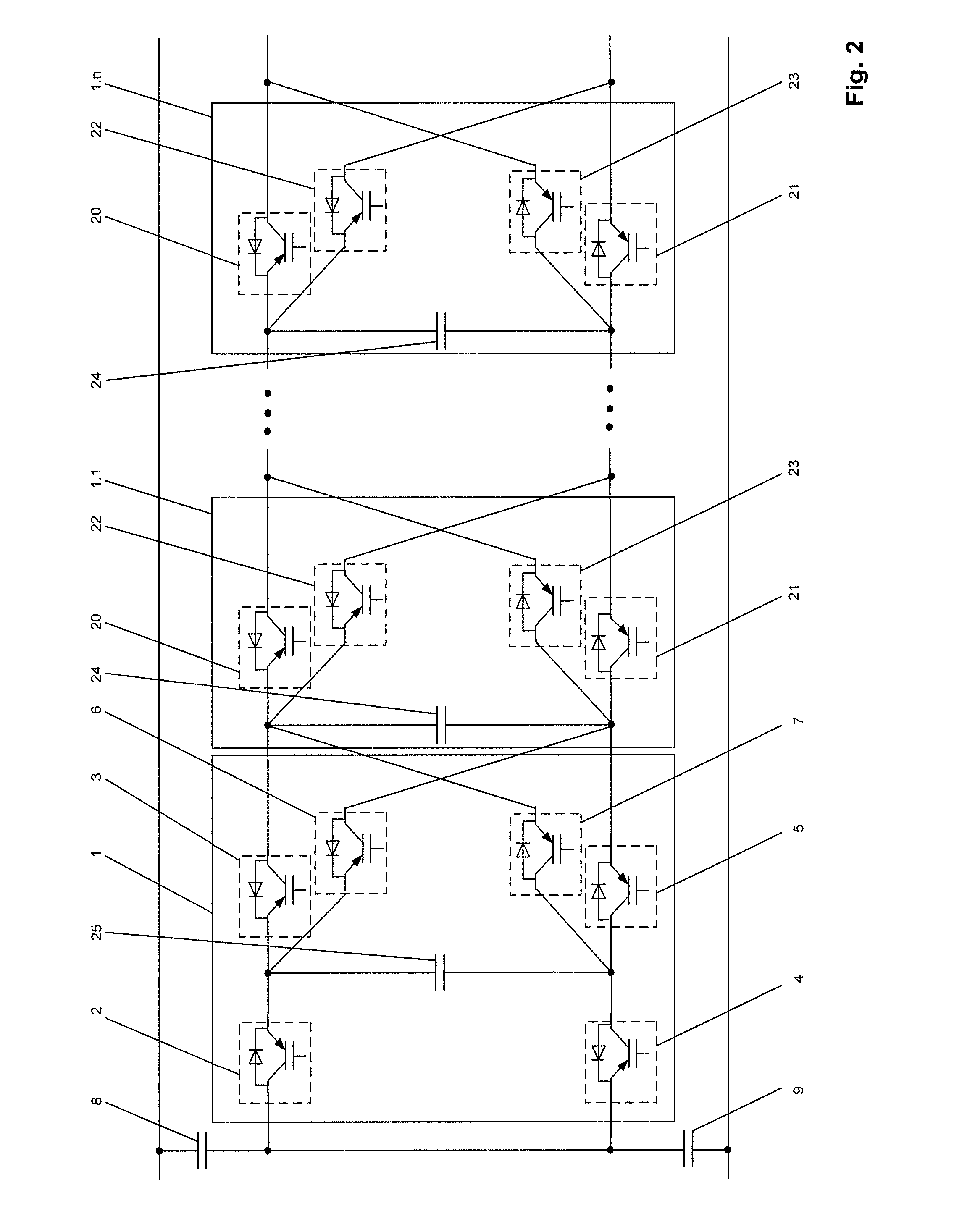
[0014]The switchgear cell according to the disclosure has a group of connection with the group of connection having a first and a second controllable bidirectional power semiconductor switch and a capacitor. The group of connection furthermore has a third, fourth, fifth and sixth controllable bidirectional power semiconductor switch with the first controllable bidirectional power semiconductor switch being connected back-to-back in series with the second controllable bidirectional power semiconductor switch and the third controllable bidirectional power semiconductor switch being connected back-to-back in series with the fourth...


PUM


Abstract

A switchgear cell having a group of connection is disclosed, with the group of connection having a first and a second controllable bidirectional power semiconductor switch and a capacitor. In order to reduce the stored electrical energy and to save space, the group of connection can have a third, fourth, fifth and sixth controllable bidirectional power semiconductor switch and the first controllable bidirectional power semiconductor switch can be connected back-to-back in series with the second controllable bidirectional power semiconductor switch, the third controllable bidirectional power semiconductor switch can be connected back-to-back in series with the fourth controllable bidirectional power semiconductor switch, the capacitor can be connected to the connection point of the first controllable bidirectional power semiconductor switch to the second controllable bidirectional power semiconductor switchand to the connection point of the third controllable bidirectional power semiconductor switch) to the fourth controllable bidirectional power semiconductor switch, the fifth controllable bidirectional power semiconductor switch can be connected to the connection point of the first controllable bidirectional power semiconductor switch to the second controllable bidirectional power semiconductor switch, and to the fourth controllable bidirectional power semiconductor switch, and the sixth controllable bidirectional power semiconductor switch can be connected to the connection point of the third controllable bidirectional power semiconductor switch to the fourth controllable bidirectional power semiconductor switch and to the second controllable bidirectional power semiconductor switch.

Description

RELATED APPLICATION[0001]This application claims priority under 35 U.S.C. §119 to European Patent Application No. 07105313.6 filed in Europe on Mar. 30, 2007, the entire content of which is hereby incorporated by reference in its entirety.TECHNICAL FIELD[0002]Converter circuits are disclosed which are, for example, based on a switchgear cell and a converter circuit for switching a multiplicity of voltage levels.BACKGROUND INFORMATION[0003]Nowadays, converter circuits are used in a wide range of power-electronic applications. A converter circuit such as this should firstly produce as few harmonics as possible on phases of an electrical AC voltage power supply system which is connected to the converter circuit, and on the other hand transmit power levels that are as high as possible with as small a number of electronic components as possible. One suitable converter circuit for switching a multiplicity of switching voltage levels is specified in DE 692 05 413 T2. This document specifie...

Claims


Application Information

Patent Timeline
IPC IPC(8): H01H47/00
CPCH02M7/483
Inventor BARBOSA, PETERSTEIMER, PETERCHAUDHURI, TOUFANN
Owner ABB RES LTD
Why Eureka
Try Eureka