Exhaust gas aftertreatment device

A technology of exhaust gas post-treatment and heating device, which is applied in the direction of electronic control of exhaust gas treatment device, diagnosis device of exhaust gas treatment device, exhaust gas treatment, etc., and can solve problems such as power loss

Active Publication Date: 2016-04-27
ROBERT BOSCH GMBH
View PDF8 Cites 0 Cited by
  • Summary
  • Abstract
  • Description
  • Claims
  • Application Information

AI Technical Summary

Problems solved by technology

In the case of previously known exhaust gas aftertreatment devices, it is disadvantageous that power is lost at the first switch and at the second switch respectively

Method used


Image

  • Exhaust gas aftertreatment device
  • Exhaust gas aftertreatment device

Examples


Embodiment Construction

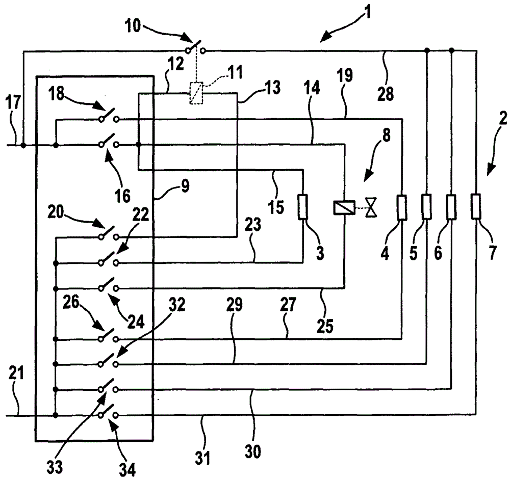
[0016] figure 1 A part of an exhaust gas aftertreatment system 1 of a motor vehicle is shown. The exhaust gas aftertreatment device 1 includes, for example, a heating device 2 with five heating elements 3 , 4 , 5 , 6 , 7 and a switching valve 8 . The heating elements 3 , 4 , 5 , 6 and 7 are designed, for example, as heating wires, heating wires or the like, and a switch valve 8 can be used to release or disconnect a not shown for discharging the heating elements 3 to 7 . Coolant circuit for heat. The heating device 2 is associated with an SCR system, wherein it serves to heat at least one line via which a working medium (for example water-urea solution) is fed to a catalytic converter (not shown). The commonly used water-urea solution freezes at approximately −10° C., so at low ambient temperatures the lines must be heated by means of the heating device 2 in order to melt or maintain the fluid state of the water-urea solution. The heat of at least one of the heating element...


PUM


Abstract

The invention relates to an automobile exhaust gas aftertreatment device (1). A heating device (2) having a plurality of heating elements (5, 6, 7) and a controller (9) matched to the heating device (2), wherein the heating elements (5, 6, 7) are fitted with a first common The switch (10) and the respective second switch (32, 33, 34) can be switched jointly by means of the first switch (10) and individually by means of the second switch (32, 33, 34). The design stipulates that the first switch (10) is arranged separately from the controller (9) and can be controlled by it.

Description

technical field [0001] The invention relates to a vehicle exhaust gas aftertreatment device with a heating device having a plurality of heating elements and a control unit associated with the heating device, wherein the heating elements are assigned a first common switch and a respective second switch and can be controlled by means of jointly with the first switch and individually with the aid of the second switch. Background technique [0002] Exhaust gas aftertreatment devices of the type mentioned at the outset are known from the prior art. They are often used in trucks. The heating device is powered via a mains line which can be switched over by means of a first switch. The individual heating elements of the heating device can also be switched individually by means of second switches assigned to them. The first switch and the second switch are usually arranged in a control unit associated with the heating device. The heating device or the heating element is thus supp...

Claims


Application Information

Patent Timeline
Patent Type & Authority Patents(China)
IPC IPC(8): F01N9/00F01N11/00F01N3/20H05B1/02
CPCF01N3/027F01N3/2013F01N3/202F01N2390/02Y02T10/12Y02A50/20
Inventor P·鲍尔M·奥恩塞尔R·鲍尔B·谢林T·霍尔斯特G·霍格尔
Owner ROBERT BOSCH GMBH
Why Eureka
Try Eureka