
Method for operating a gas and steam turbine plant and a gas and steam turbine plant for this purpose

a gas and steam turbine and gas turbine technology, which is applied in the direction of machines/engines, mechanical equipment, light and heating equipment, etc., can solve the problems of high manufacturing cost, high manufacturing cost, and high manufacturing cost, and achieve low-cost design, high reliability, and high operational safety.

Inactive Publication Date: 2010-04-15
SIEMENS AG
View PDF14 Cites 20 Cited by
  • Summary
  • Abstract
  • Description
  • Claims
  • Application Information

AI Technical Summary

Benefits of technology

[0013]The underlying object of the invention is thus to specify a method for operation of a gas and steam turbine plant of the type mentioned at the start but with high reliability and high operational safety that can be adapted especially flexibly to different types of operating states of the plant and that makes possible an especially low-cost design of the components of the respective evaporator circuit. In addition a gas and steam turbine plant suitable for executing the method is to be specified.
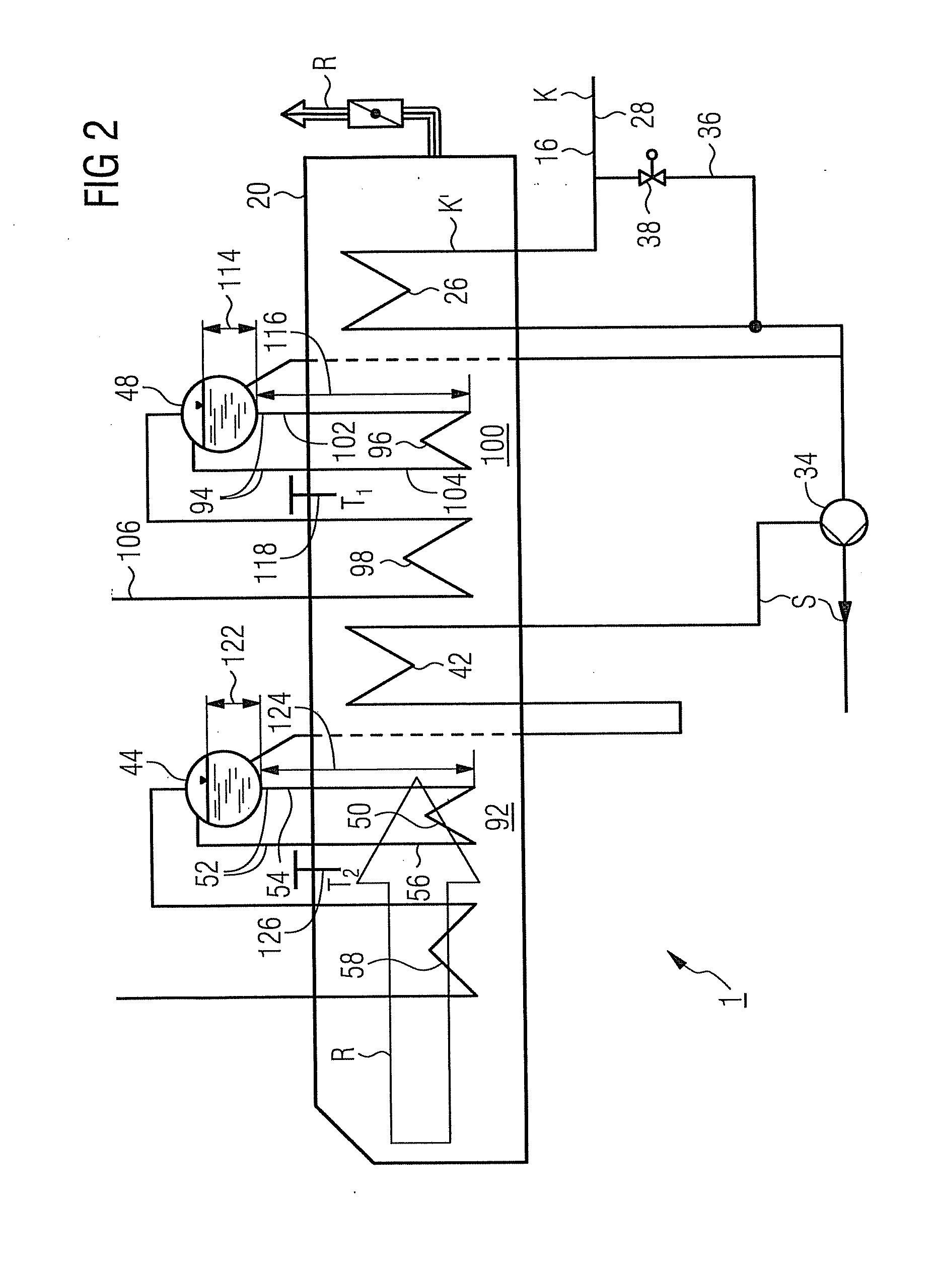
[0015]The invention is based on the idea that, because of the progress achieved recently in materials technology and materials development for evaporator heating pipes compared to the versions previously occurring in the technical field. a design of a gas and steam turbine system is both concealable from a technical standpoint and is also competitive in practice under the given economic general conditions in which for at least part of the time during particular operating states part or also completely dry operation of a evaporator circuit, given a fall in the liquid level in the downpipes below the level of the steam collection drum, is tolerable.
[0024]Specifically with a three-pressure system with a condensate preheater, an MD economizer connected downstream from the condensate preheater for the feed water of the MD evaporator and an HD economizer connected downstream from the MD economizer for the feed water of the HD stage, the opening of the condensate preheater bypass line or the bypass line of the MD economizer leads in the standard case to, as described in DE 100 04 187 C1, the HD evaporator being arranged on the flue gas side before the MD evaporator and this in its turn before the ND evaporator, with the advantageous ancillary effect that now the evaporator circuit of the HD stage is supplied with comparatively cooler feed water, so that a comparatively large amount of heat is withdrawn from the flue gas of the gas turbine even in the entry area of the waste gas steam generator. The temperature stress—moderate in any event by comparison with the high-pressure stage—in the area of the MD and ND heating surfaces is reduced by this especially quickly and effectively if required. It is precisely with this type of effective demand-activatable safety measure that a temporary drying out of the MD and / or the ND evaporator circuit can thus be tolerated especially well.
[0029]The benefits obtained with the invention consist especially of making it possible, by the explicit design of the plant architecture and the associated safety and monitoring systems, with a gas and steam turbine plant with a waste heat steam generator, for an evaporator system based on the natural circulation principle, especially the MD and / or the ND evaporator system, to be operated without danger at a water level far below the currently defined minimum water level or even to let the heating surfaces dry out without having to stop the operation of the waste heat steam generator or the gas turbine. In particular setting of flexible minimum water levels in the respective evaporator circuit as a function of a specific operating mode is possible without any safety implications.
[0030]It can be shown that such a concept also fulfils the safety standards defined by the new DIN IEC 61508 and DIN IEC 61511 norms and even exceeds them. The risk of rapid disconnection of the waste heat steam generator on rapid closing of the steam turbine control valves or with rapid changes in loads namely falls considerably if the water level in the evaporator circuit can fall below the drum level without danger. Thus the availability of the gas and steam turbine system is further increased, especially for rapid starts which are becoming increasingly important to compensate for short-term demand and supply variations in the power network. With gas and steam turbine plants in particular without a bypass chimney valve, a lower fast deactivation risk to the waste heat steam generator results in lower stresses and thus fewer equivalent operating hours for the gas turbine. In such cases, with the safety level remaining the same, the maintenance intervals on the gas turbine can be increased.
[0031]In addition the inventive concept makes possible a low-cost design and construction of components of the evaporator system which are usually very costly to manufacture, since in particular the MD and ND steam collection drums can be designed to be more compact than was previously necessary. This is of special relevance within the framework of the “sleeping mode” mode of operation described above, where the low-pressure bypass station for the ND evaporator is omitted, since the increase in drum size otherwise required to execute its operating mode can now be less or can even be dispensed with altogether. Finally the control outlay for adhering to condensate preheater and economizer inlet temperatures with oil operation is lower than before.

Problems solved by technology

This is however associated with a correspondingly high manufacturing outlay and thereby also with high manufacturing costs.
In accordance with the particular relevance attributed to adhering to the minimum water level in the steam collection drum, in existing plants there is also a three-fold redundant measurement or monitoring of the current fill level related to the drum or to the upper edge of the downpipes, which requires a relatively expensive design of the associated safety facilities.
In the interests of highest possible system availability such a fast deactivation is however definitely not desirable.
These can for example cause fluctuations in the drum water levels of the MD and ND drums and an undesirably high increase in pressure in the ND drum.
By contrast with the original alignment of the concept, a low-pressure diversion station, which reduces the fall in the water level during a rapid deactivation of the steam turbine, cannot therefore be completely dispensed with.

Method used


Image

  • Method for operating a gas and steam turbine plant and a gas and steam turbine plant for this purpose
  • Method for operating a gas and steam turbine plant and a gas and steam turbine plant for this purpose
  • Method for operating a gas and steam turbine plant and a gas and steam turbine plant for this purpose

Examples


Embodiment Construction

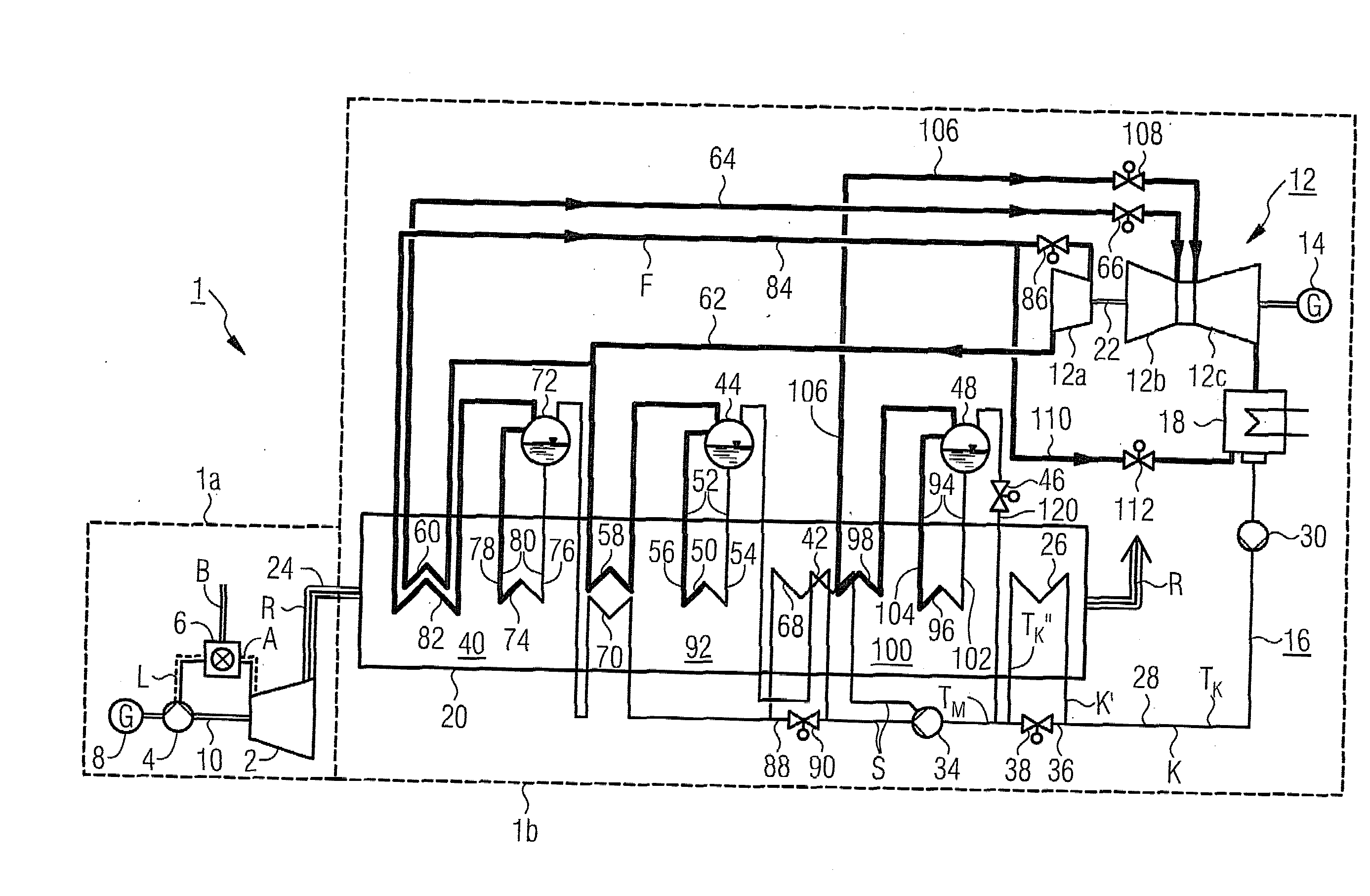
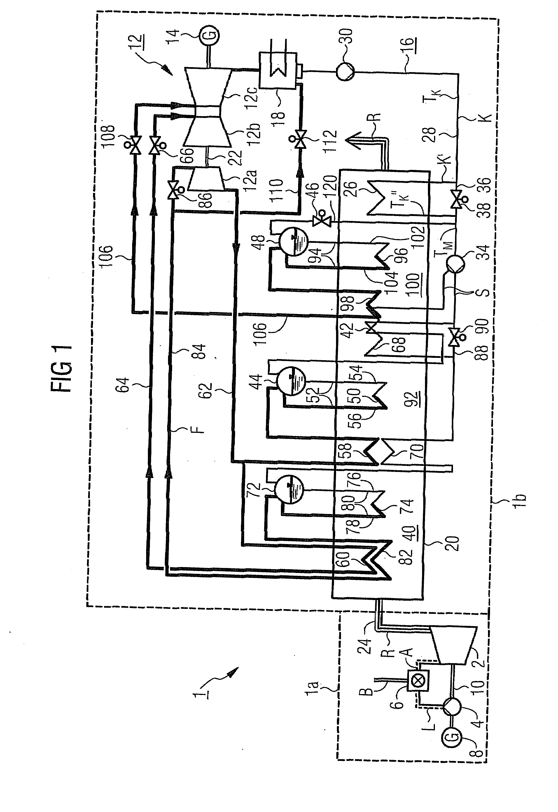
[0037]The gas and steam turbine plant 1 in accordance with FIG. 1 comprises a gas turbine system 1a and a steam turbine system1b.

[0038]The gas turbine system 1a comprises a gas turbine 2 with connected air compressor 4 and a combustion chamber connected upstream from the gas turbine 2, in which fuel B with the addition of compressed air from the air compressor 4 is burnt for the operating medium or combustion gas A for the gas turbine 2, The gas turbine 2 and the air compressor 4 as well as a generator 8 sit on a common turbine shaft 10.

[0039]The steam turbine system 1b comprises a steam turbine 12 with generator 14 coupled to it and in a flow medium circuit 16 embodied as a water-steam circuit, a condenser 18 connected downstream from the steam turbine 12 as well as a waste heat steam generator 20. The steam turbine 12 features a first pressure stage or a high-pressure part 12a and a second pressure stage or a medium-pressure part 12b as well as a third pressure stage or a low-pre...


PUM


Abstract

A method for operating a gas and steam turbine plant is provided. In the plant, the flue gas that escapes from a gas turbine is routed through a waste gas steam generator and where a flow medium that is used to drive a steam turbine is conducted in a flow medium circuit that includes several pressure stages. At least one of the pressure stages has an evaporator circuit with a steam collection drum that has a plurality of downpipes connected to the steam collection drum and a plurality of rising pipes downstream of the downpipes that are likewise connected to the steam collection drum and are heated by the flue gas in the waste heat steam generator. The height of the fluid column formed by the flow medium in the downpipes is monitored and a transient dry operation of the evaporator circuit can thus be detected and safeguarded against.

Description

CROSS REFERENCE TO RELATED APPLICATIONS[0001]This application is the U.S. National Stage of International Application No. PCT / EP2008 / 050954, filed Jan. 28, 2008 and claims the benefit thereof. The International Application claims the benefits of European Patent Office application No. 07002014.4 EP filed Jan. 30, 2007, both of the applications are incorporated by reference herein in their entirety.FIELD OF INVENTION[0002]The invention relates to a method for operating a gas and steam turbine plant in which flue gas exiting from a gas turbine is routed via a waste heat steam generator and in which a flow medium used for driving a steam turbine is conducted in a flow medium circuit comprising a number of pressure stages, with at least one of the pressure stages having an evaporator circuit with a steam collection drum with a number of downpipes connected to the steam collection drum and with a number of riser pipes downstream from the downpipes, likewise connected to the steam collecti...

Claims


Application Information

Patent Timeline
IPC IPC(8): F01K23/10F02C6/00
CPCF01K23/108
Inventor BRUCKNER, JANHESS, RUDOLFSCHMID, ERICH
Owner SIEMENS AG
Learn More