Pneumatic quick connector

A fast, female joint technology, applied in the direction of mechanical equipment, couplings, etc., can solve the problems of cumbersome on and off operations, large air pressure loss, and small gas flow area, so as to solve the problems of more pressure loss and reduced air pressure Loss, the effect of preventing air leakage

Inactive Publication Date: 2010-12-08
楼松乔
View PDF5 Cites 22 Cited by
  • Summary
  • Abstract
  • Description
  • Claims
  • Application Information

AI Technical Summary

Problems solved by technology

The on-off operation of this structure is cumbersome, and at the same time, the ga

Method used


Image

  • Pneumatic quick connector
  • Pneumatic quick connector
  • Pneumatic quick connector

Examples


Example Embodiment

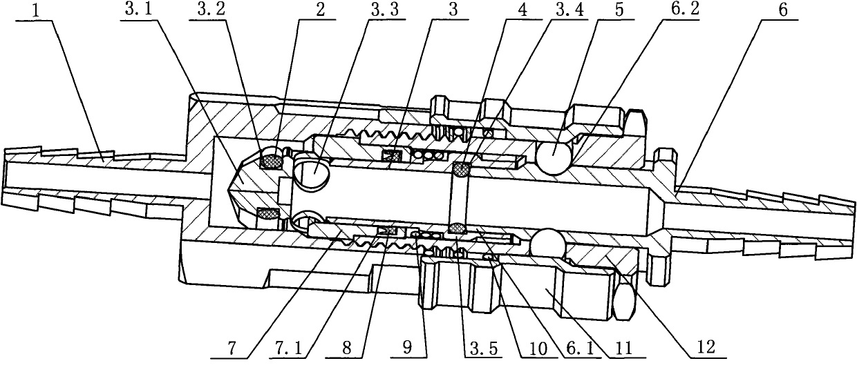
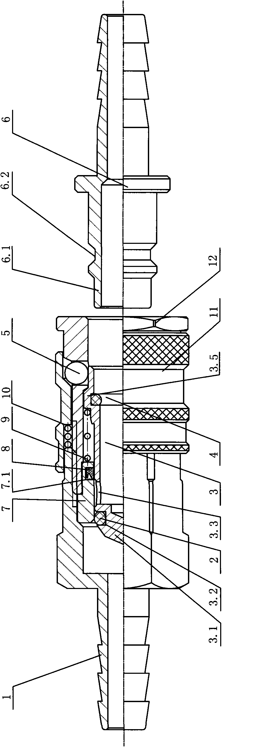
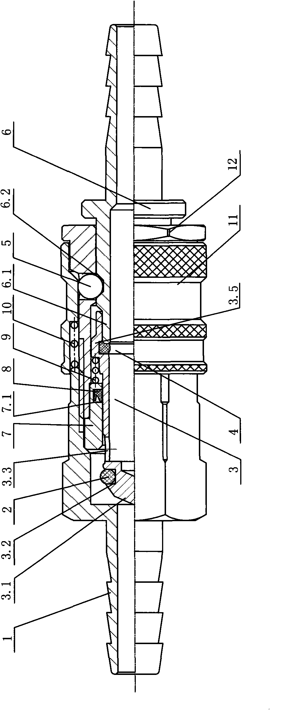
[0014] Such as figure 1 , figure 2 As shown, the present invention is a pneumatic quick connector, which includes a female connector 1 connected with an air inlet pipe and a male connector 6 connected with an outlet pipe. A locking sleeve 12 is fixedly installed on the air outlet end of the female connector 1. The locking sleeve 12 and the female connector 1 are connected by threads. A guide sleeve 7 is sandwiched between the locking sleeve 12 and the inner wall of the female connector 1, and a check valve core 3 that can move back and forth is movably inserted in the inner hole of the guide sleeve 7. The inner wall of the guide sleeve 7 is provided with a groove 7.1, which is embedded with a Y-shaped sealing ring 8. When the check valve core 3 is inserted into the inner hole of the guide sleeve 7, the Y-shaped sealing ring 8 is compared with other sealing rings. The friction force is smaller, and it is not easy to damage or fall off, which facilitates the installation of the ...


PUM


Abstract

The invention relates to a pneumatic quick connector which comprises a female connector connected with an air inlet pipe and a male connector connected with an air outlet pipe, wherein an air outlet end of the female connector is fixedly provided with a locking sleeve; the inner holes of the female connector and the locking sleeve are internally provided with a check valve core with an exhaust channel; an air inlet end of the male connector is communicated with the exhaust channel of the check valve core; a guide sleeve is clamped between the locking sleeve and the inner wall of the female connector; the check valve core is movably penetrated in the inner hole of the guide sleeve; a valve core spring is supported between the guide sleeve and the check valve core; the head part of the check valve core is sealed, forms a taper shape and is opposite to the air inlet direction of the female connector; the excircle of the head part of the check valve core is provided with a sealing ring slot, and an O-shaped sealing ring is embedded in the sealing ring slot; and the side wall at the front end of the check valve core is provided with an air inlet communicated with the exhaust channel of the check valve core. The invention can realize the quick on-off of an air conveyer pipeline, has a check function for preventing air leakage during turning off and also has the advantages of less loss and convenient and quick on-off operations.

Description

Technical field: [0001] The invention relates to a joint installed in a high-pressure gas transmission pipeline, in particular to a pneumatic quick joint capable of fast on and off, and has a non-return function. Background technique: [0002] Pneumatic quick connector is a special connection device that can quickly connect or disconnect the gas pipeline to realize the quick disassembly of the pipeline. It has the function of quick plug-in and one-way check after disconnection. In the current packaging machinery, medical machinery, electronic equipment, welding equipment and other mechanical and electrical equipment industries, compressed gas is widely used, such as various pneumatic tools powered by compressed air, compressed gas such as oxygen and hydrogen, etc. In the specific use of compressed gas, pneumatic quick connectors are often installed on the gas pipeline. The check valve structure and flow channel design of the pneumatic quick connector are the most important ...

Claims


Application Information

Patent Timeline
IPC IPC(8): F16L37/086F16L37/40
Inventor 楼松乔楼仲宇
Owner 楼松乔
Why Eureka
Try Eureka