RFID tag system

a technology of rfid tags and tags, applied in the direction of burglar alarm mechanical actuation, instruments, transportation and packaging, etc., can solve the problem of inability to identify with a predefined radio frequency, and achieve the effect of reducing manufacturing costs, quick and accurate fault detection, and improving applicability and economic efficiency

a technology of rfid tags and tags, applied in the direction of burglar alarm mechanical actuation, instruments, transportation and packaging, etc., can solve the problem of inability to identify with a predefined radio frequency, and achieve the effect of reducing manufacturing costs, quick and accurate fault detection, and improving applicability and economic efficiency

US20080238675A1Inactive Publication Date: 2008-10-02GIGATEK

Image

  • RFID tag system
  • RFID tag system
  • RFID tag system

Examples


Embodiment Construction

[0026]The features and the advantages of the present invention will be more readily understood upon a thoughtful deliberation of the following detailed description of a preferred embodiment of the present invention with reference to the accompanying drawings.

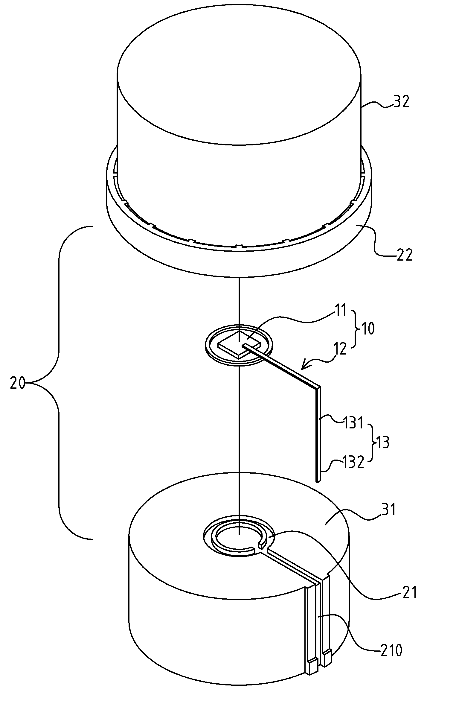
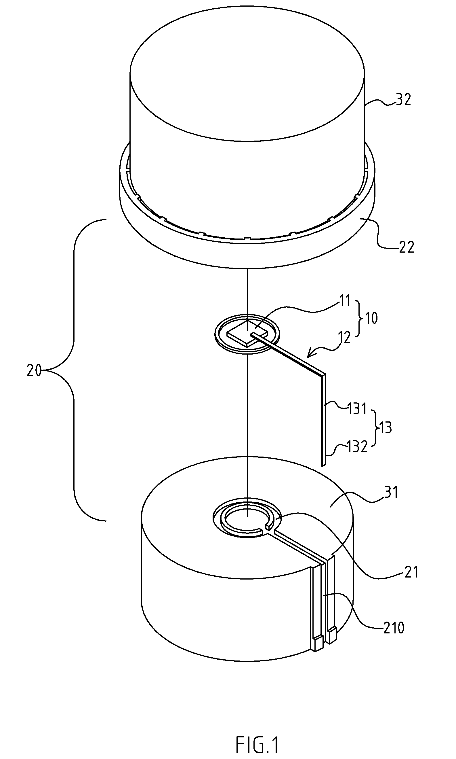
[0027]FIGS. 1 and 2 depict preferred embodiments of improved structure of an RFID tag of the present invention. The embodiments are provided only for explanatory purposes. The RFID tag 10 is attached onto an object 20, which may be packing or packaging (e.g. cap or packaging bag), or a seal, or a lifting card.

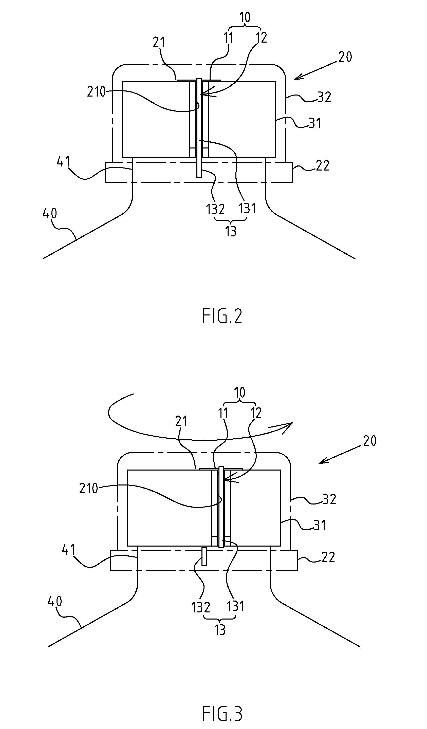
[0028]The object 20 comprises a first portion 21 and a second portion 22, which can be separated from or misaligned with each other.

[0029]The RFID tag 10 comprises a telecom IC 11 (e.g. silicon chip), and an antenna 12 linked to the telecom IC 11, of which a protruding end 13 is defined at the antenna 12. The telecom IC 11 is assembled on the first portion 21 of object 20. The protruding end 13 of antenna 12 comprises a fir...


PUM


Abstract

The present invention provides an applied RFID tag system with the RFID tag assembled between the first and second portions of an object. When the first and second portions are separated or misaligned, the RFID tag will be deformed and damaged, making it impossible to be identified with a predefined radio frequency, namely, it cannot be identified by card reader. According to the damage information, the operator could learn the unsealing or loosening state of the products, thus ensuring quick and accurate quality control and improved fault detection.

Description

CROSS-REFERENCE TO RELATED U.S. APPLICATIONS[0001]Not applicable.STATEMENT REGARDING FEDERALLY SPONSORED RESEARCH OR DEVELOPMENT[0002]Not applicable.NAMES OF PARTIES TO A JOINT RESEARCH AGREEMENT[0003]Not applicable.REFERENCE TO AN APPENDIX SUBMITTED ON COMPACT DISC[0004]Not applicable.BACKGROUND OF THE INVENTION[0005]1. Field of the Invention[0006]The present invention relates generally to a system with an RFID tag, and more particularly to an innovative RFID tag that allows first and second portions of the tagged object to be separated or misaligned, thus serving the purpose of fast and accurate product control.[0007]2. Description of Related Art Including Information Disclosed Under 37 CFR 1.97 and 37 CFR 1.98[0008]A Radio Frequency Identification (RFID) tag refers generally to components comprising RF IC (Integrated Circuit) chips below 2 cm and antenna. The special reader / writer allows reading or writing data externally. Due to the features of the RFID, the product properties a...

Claims


Application Information

Patent Timeline
02 Oct 2008
Publication
US20080238675A1
IPC
G08B13/24
CPC
B65D55/028; B65D79/02; B65D2203/10; G06K19/07798
Inventors
YANG, WEI-SHENG