
Method and apparatus for adaptively converting frame rate based on motion vector, and display device with adaptive frame rate conversion function

a frame rate and motion vector technology, applied in the field of image display devices, can solve the problems of reducing generating artifacts due to motion compensation errors, and error occurring even in a compensated motion vector, so as to reduce the size of the input image, minimize the artifact generated in the boundary of an interpolation imag

Inactive Publication Date: 2008-10-02
SAMSUNG ELECTRONICS CO LTD
View PDF5 Cites 29 Cited by
  • Summary
  • Abstract
  • Description
  • Claims
  • Application Information

AI Technical Summary

Benefits of technology

[0013]The present invention provides an interpolation image generation method for effectively detecting a motion error of a boundary area of an interpolation image and canceling a motion prediction error and a motion compensation error in the detected boundary area.
[0014]The present invention also provides an interpolation image generation apparatus for minimizing a motion prediction error and a motion compensation error generated in a boundary of an image having a large motion, when frames are interpolated using a motion prediction and motion compensation method.
[0015]The present invention also provides a display device for generating a correct interpolation image corresponding to a boundary of an image by increasing motion compensation accuracy by detecting in advance an area in which an error occurs from an image having a large motion and minimizing a motion prediction error.
[0027]Accordingly, artifacts generated in a boundary of an interpolation image can be minimized, and an input image can be displayed without reducing the size of the input image.

Problems solved by technology

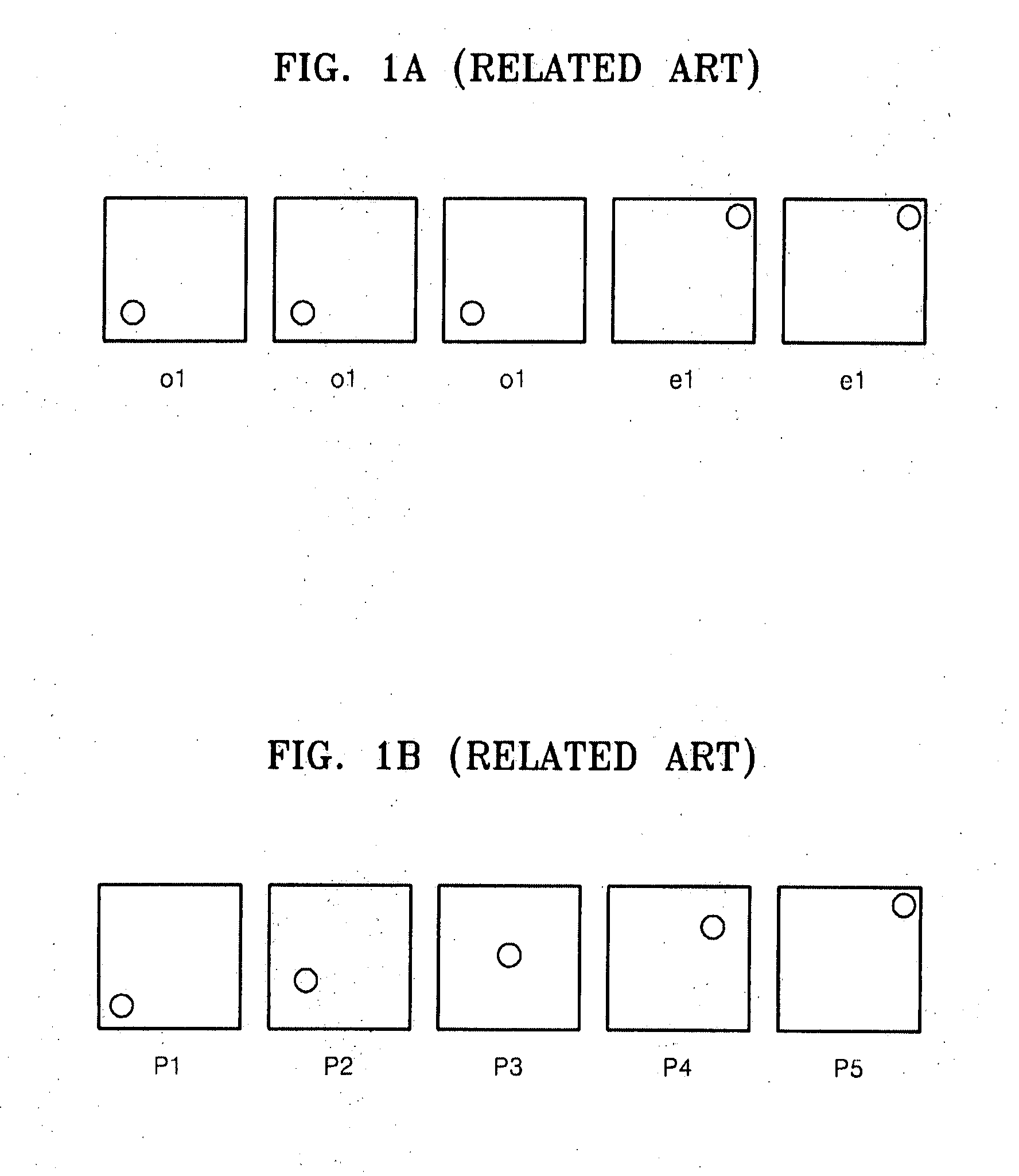
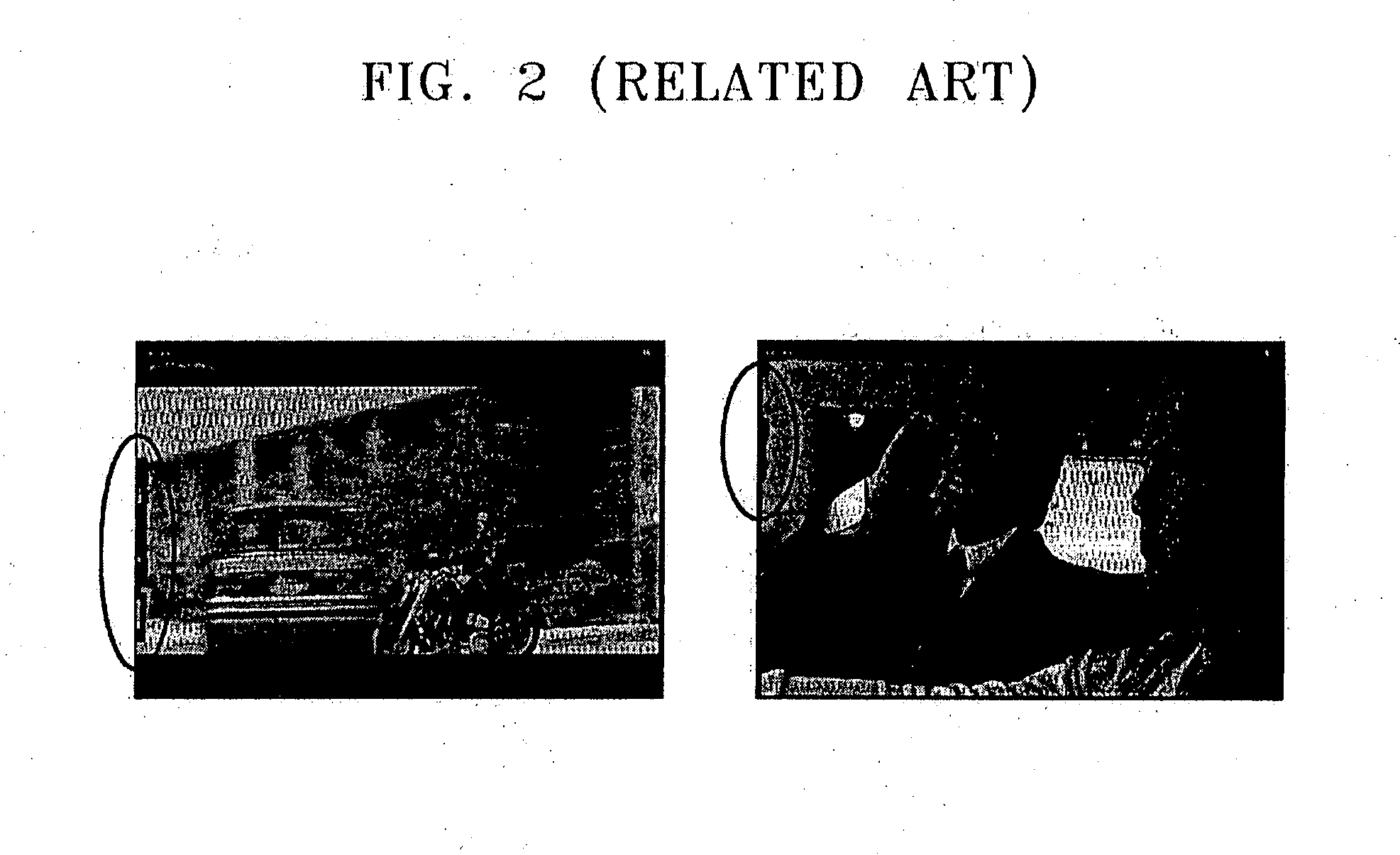
In all display devices up-converting a frame rate using a motion prediction and motion compensation method, artifacts due to a motion compensation error are generated in an edge portion of each image.
These artifacts are caused by a motion error of an uncovered area, which is generated in a previous frame or field or a subsequent frame or field.
In addition, if a local motion occurs inside a boundary of a panning image due to the movement of a camera or an image in which a dominant motion significantly occurs, an error occurs even in a compensated motion vector.
In this case, a viewer cannot help but view a screen that is a little bit smaller than an actual screen, and if a circumference portion of an image exists in the image, a motion compensation error still occurs.

Method used


Image

  • Method and apparatus for adaptively converting frame rate based on motion vector, and display device with adaptive frame rate conversion function
  • Method and apparatus for adaptively converting frame rate based on motion vector, and display device with adaptive frame rate conversion function
  • Method and apparatus for adaptively converting frame rate based on motion vector, and display device with adaptive frame rate conversion function

Examples


Embodiment Construction

[0038]FIG. 3 is a block diagram of an interpolation image generation apparatus according to an exemplary embodiment of the present invention.

[0039]Referring to FIG. 3, an interpolation image generation apparatus 300 includes a motion predictor 310 and a motion compensator 330.

[0040]The motion predictor 310 receives an image unit of an input image. The image unit is a fundamental unit of an image signal, for example, a field or frame of the image signal. As illustrated in FIG. 3, the motion predictor 310 receives a previous image unit and a subsequent image unit, and calculates a motion vector from the previous image unit and the subsequent image unit. The motion vector is transmitted to the motion compensator 330.

[0041]The motion compensator 330 receives the previous image unit and the subsequent image unit, and receives the motion vector from the motion predictor 310. The motion compensator 330 includes a boundary detector 350, a motion vector re-setting unit 370, and an artifact c...


PUM


Abstract

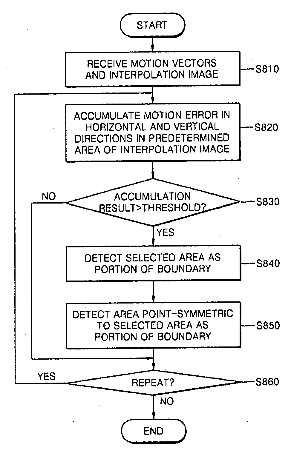
An interpolation image generation method and apparatus for adaptively converting a frame rate based on a motion vector, and a display device having an adaptive frame rate conversion function are provided. The interpolation image generation method includes an interpolation image generation process calculating motion vectors from a previous image unit and a subsequent image unit that are continuous and generating an interpolation image using the motion vectors; a motion error boundary detection process detecting an area, in which a motion error determined from the motion vectors is greater than a predetermined value, as a boundary area of the interpolation image; and a motion compensation process compensating for a motion error inside the detected boundary area based on a dominant direction of the motion vectors using at least one of the previous image unit and the subsequent image unit.

Description

CROSS-REFERENCE TO RELATED PATENT APPLICATION[0001]This application claims priority from Korean Patent Application No. 10-2007-0030051, filed on Mar. 27, 2007 in the Korean Intellectual Property Office, the disclosure of which is incorporated herein in its entirety by reference.BACKGROUND OF THE INVENTION[0002]1. Field of the Invention[0003]The present invention relates to an image display device, and more particularly, to a method and apparatus for adaptively converting a frame rate based on a motion vector, and a display device with an adaptive frame rate conversion function.[0004]2. Description of the Related Art[0005]Television (TV) signals received using an interface method have a 60-Hz frame rate in National Television Standards Committee (NTSC) systems, and a 50-Hz frame rate in Phase Alternating Line (PAL) systems. However, since TV signals are received at 24 Hz in terms of movies, a movie frame rate is converted generally using 3:2 or 2:2 pull-down, and the frames are displ...

Claims


Application Information

Patent Timeline
IPC IPC(8): H04N11/02G06K9/32
CPCG06T3/4038H04N5/145H04N7/0127H04N7/014G09G3/36H04N7/01
Inventor SHIN, DONG-HYUKHAN, SEUNG-HOONKIM, DAE-HYUN
Owner SAMSUNG ELECTRONICS CO LTD
Learn More