Information device operation apparatus
- Summary
- Abstract
- Description
- Claims
- Application Information
AI Technical Summary
Benefits of technology
Problems solved by technology
Method used
Image

Examples
first embodiment
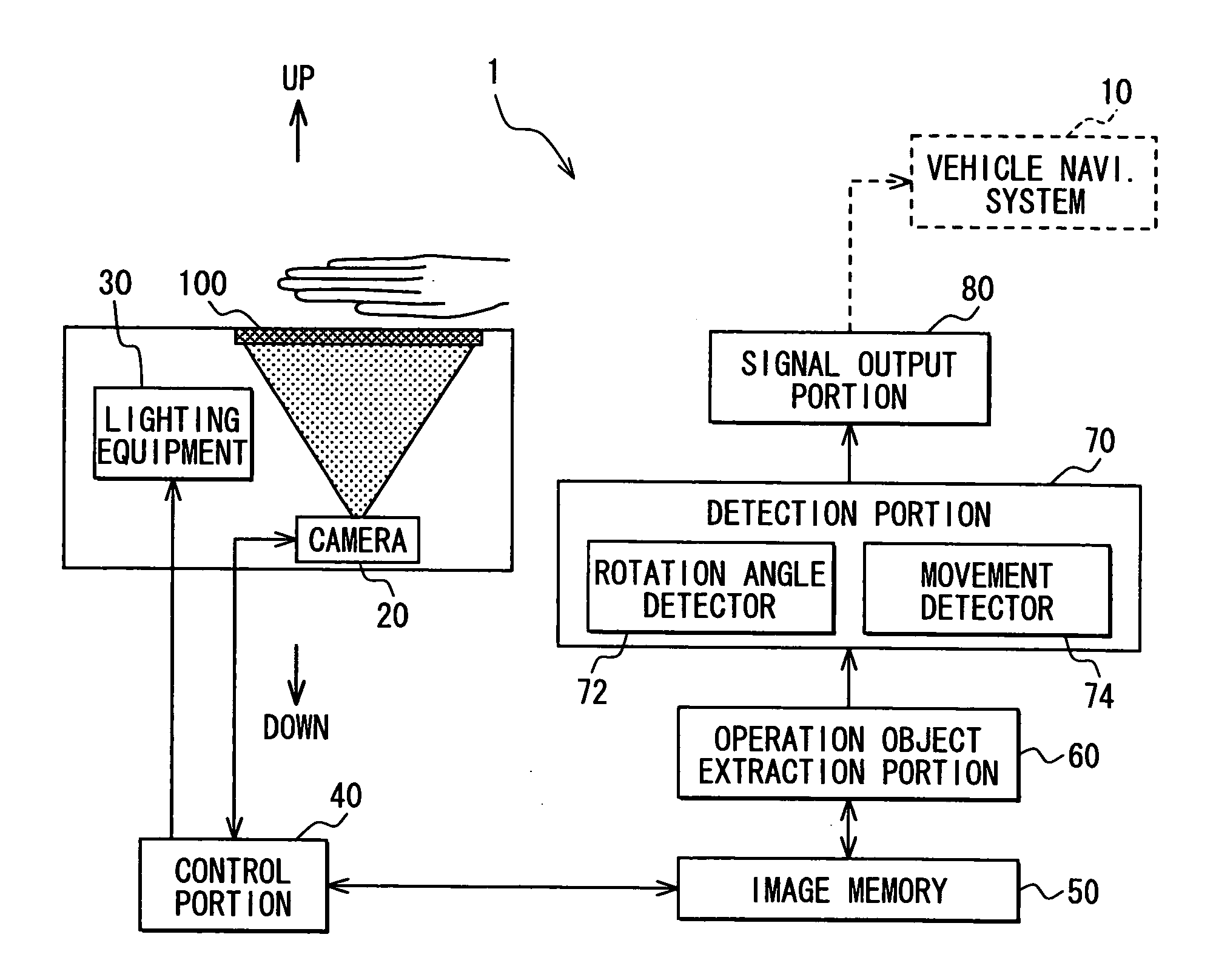
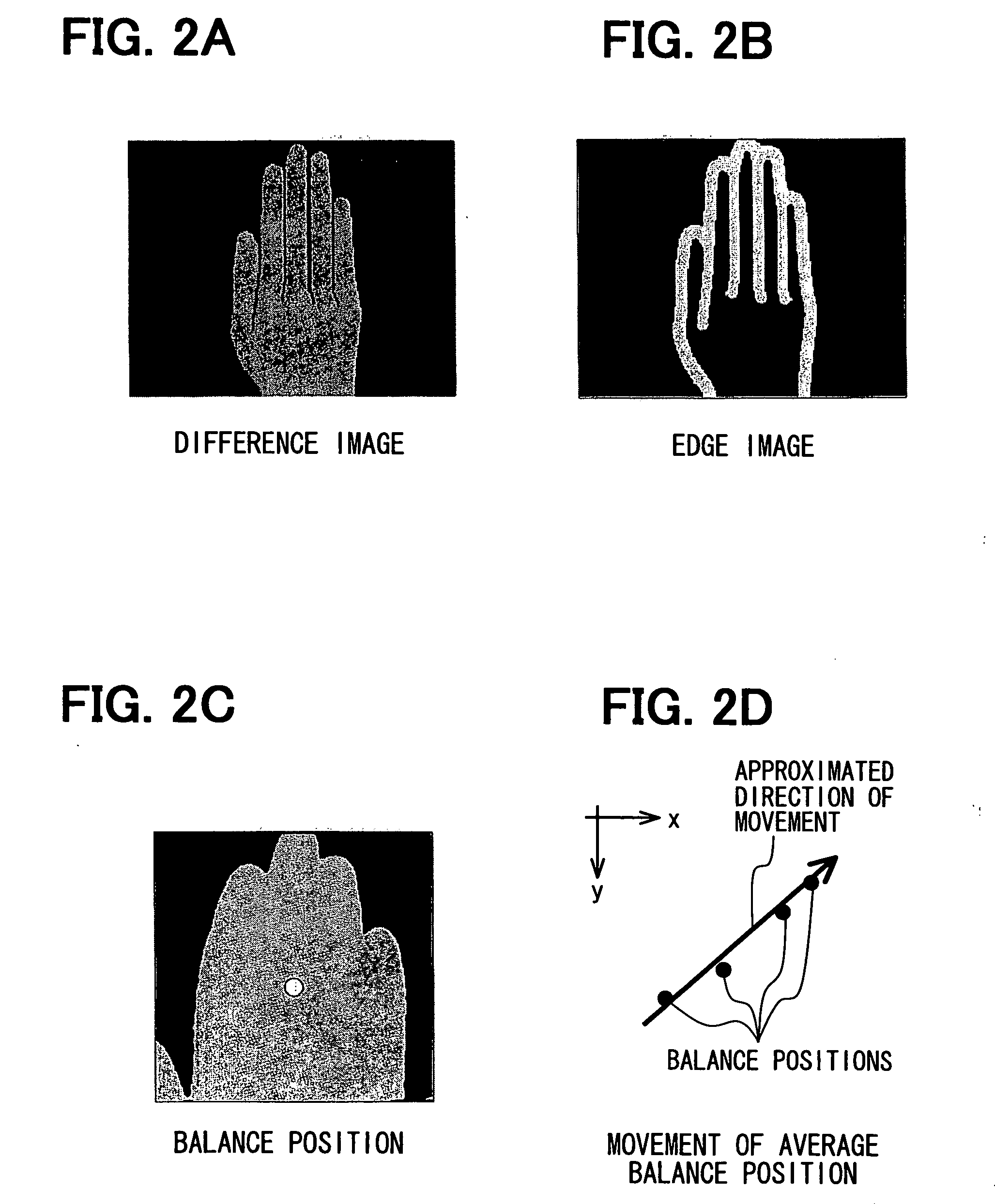
[0042]Firstly, a vehicle navigation operation apparatus 1 for operating a vehicle navigation system 10 is described referring to FIGS. 1 and 2. FIG. 1 is a schematic block diagram illustrating a configuration of the vehicle navigation operation apparatus 1, and FIGS. 2A to 2D are diagrams for explaining image processing for detecting a rotation angle, a movement direction, and a movement amount of the hand of the driver. The hand serves as an operation object.
[0043]As shown in FIG. 1, the vehicle navigation operation apparatus 1 extracts the hand of the driver by the image processing, the hand being used for operating the vehicle navigation system 10. The vehicle navigation operation apparatus 1 includes a camera 20, a lighting equipment 30, a control portion 40, an image memory 50, an operation object extraction portion 60, a detection portion 70, and a signal output portion 80.
[0044]The camera 20 is a small CCD camera or a CMOS camera and is located at a position for capturing an ...
second embodiment
[0064]The vehicle navigation operation apparatus 1 of the first embodiment outputs signals for operation of the vehicle navigation system 10 based on the movement of the hand of the driver above the touch sensitive panel 100, the movement being made in the two dimensional system or on a plane, for example. In contrast, a vehicle navigation operation apparatus 2 of the second embodiment is configured to operate the vehicle navigation system 10 based on the movement of the hand of the driver in a three dimensional space and is described referring to FIG. 3 and FIG. 4. Note that, because the vehicle navigation operation apparatus 2 has a similar structure similar to the vehicle navigation operation apparatus 1 of the first embodiment, components of the vehicle navigation operation apparatus 2 similar to the components of the vehicle navigation operation apparatus 1 are indicated by the same numerals, and the explanations thereof are omitted.
[0065]FIG. 3 is a schematic block diagram ill...
third embodiment
[0093]Next, a vehicle navigation operation apparatus 3 will be described referring to FIGS. 8A and 8B. Note that in the vehicle navigation operation apparatus 3, the movement of the hand of the driver is detected by a distance sensor but not by the camera for capturing the image. Note that, the vehicle navigation operation apparatus 3 has a similar structure similar to the vehicle navigation operation apparatus 2 of the first embodiment. Thus, components of the vehicle navigation operation apparatus 3 similar to the components of the vehicle navigation operation apparatus 2 are indicated by the same numerals, and the explanations thereof are omitted.
[0094]FIG. 8A is a schematic block diagram illustrating a configuration of the vehicle navigation operation apparatus 3. As shown in FIG. 8B, the vehicle navigation operation apparatus 3 includes ultrasonic wave distance sensors 90 having directivity at four corners of the touch sensitive panel 100.
[0095]The space rotation angle detector...
PUM
 Abstract
Description
Claims
Application Information
 - Generate Ideas
- Intellectual Property
- Life Sciences
- Materials
- Tech Scout
- Unparalleled Data Quality
- Higher Quality Content
- 60% Fewer Hallucinations
Browse by: Latest US Patents, China's latest patents, Technical Efficacy Thesaurus, Application Domain, Technology Topic, Popular Technical Reports.
© 2025 PatSnap. All rights reserved.Legal|Privacy policy|Modern Slavery Act Transparency Statement|Sitemap|About US| Contact US: help@patsnap.com