Beam position sensor

a position sensor and beam technology, applied in the field of fiber optic communication equipment, can solve the problems of significant changes in environmental conditions that could require a recalibration

Active Publication Date: 2008-10-02
CROSSFIBER +1
View PDF3 Cites 17 Cited by
  • Summary
  • Abstract
  • Description
  • Claims
  • Application Information

AI Technical Summary

Benefits of technology

[0023]In preferred embodiments the first and second fiber-microlens positioning arrays include a positioning plate with lithographically-defined sub-micron V-groove alignment features for alignment a set of ribbon optical fibers. The fibers are first positioned

Problems solved by technology

However, significant changes in environment

Method used


Image

  • Beam position sensor
  • Beam position sensor
  • Beam position sensor

Examples


first preferred embodiment

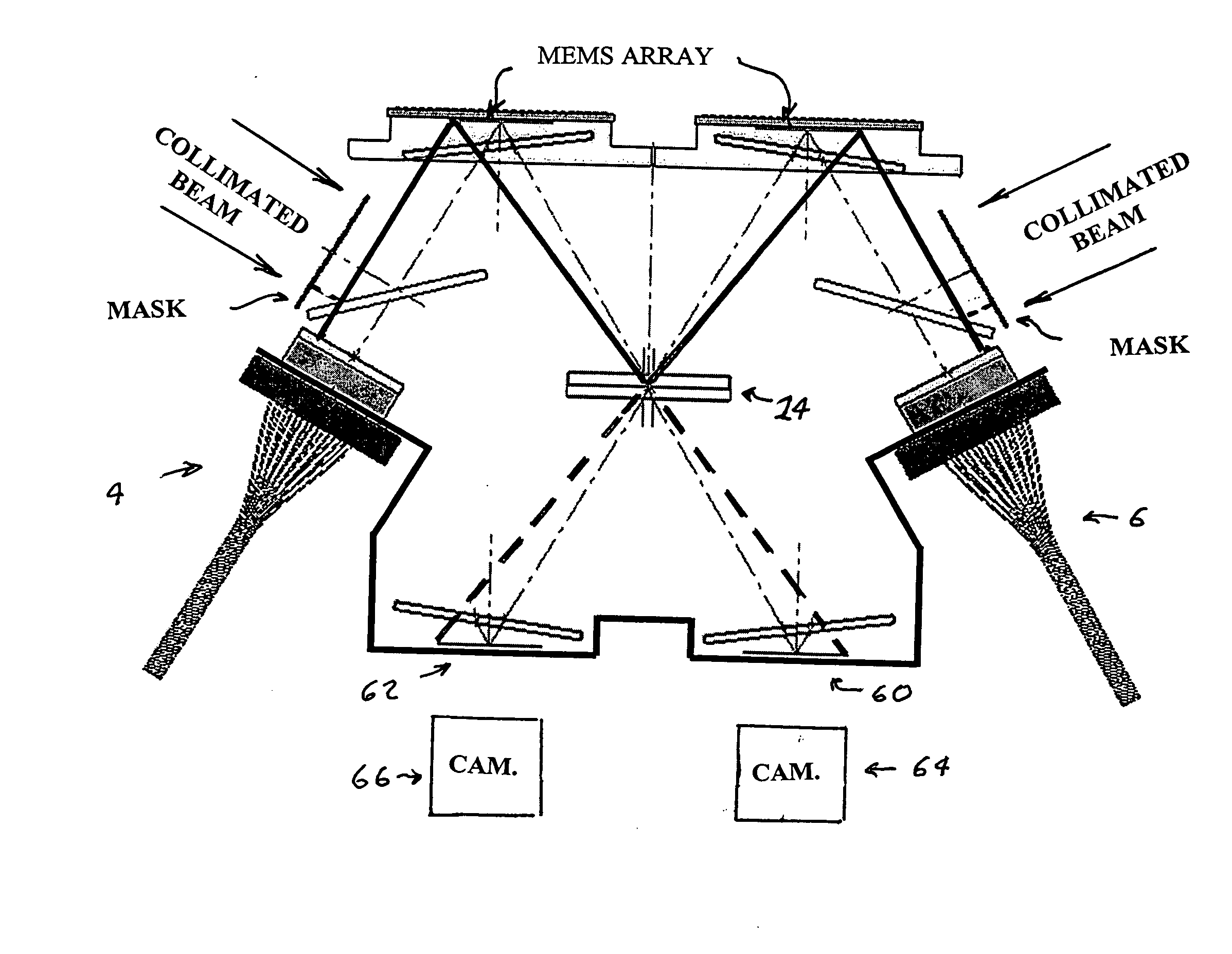
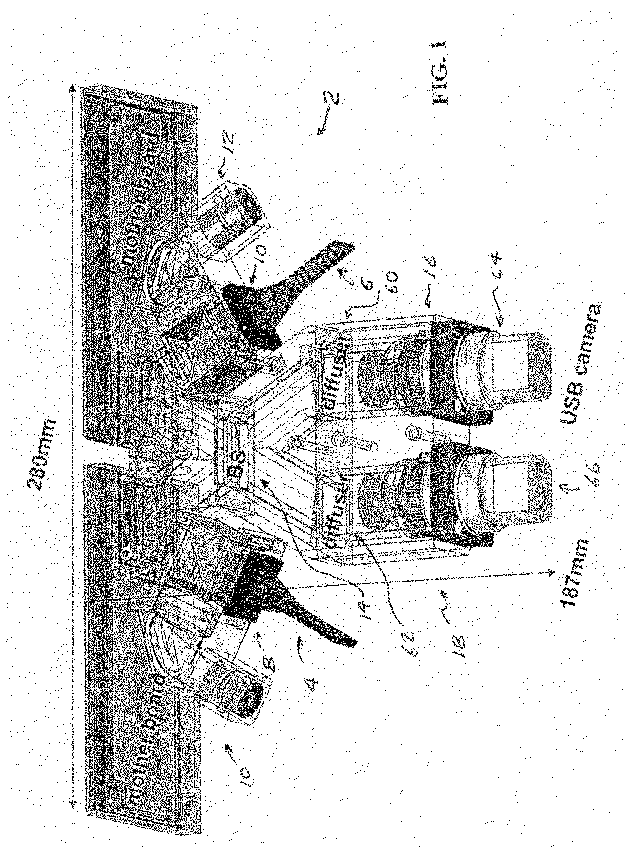
[0040]FIG. 1 shows at 2 a prospective view of features of a first preferred embodiment of the present invention. This first preferred embodiment is an optical switch module 2. Its size and general shape is described by the drawing in FIG. 4 as compared to a adult human hand. This optical switch module 2 is designed for switching optical communication beams carried by the fibers of a first 128 (8×16) optical fiber bundle such as bundle 4 as shown in FIG. 1 into the fibers of a second 128 optical fiber bundle such as bundle 6. The beams in any fiber of bundle 4 can be switched into any fiber of bundle 6. The switch is symmetrical and can be operated in either direction so that any fiber of bundle 6 can be switched into any fiber of bundle 4.

[0041]We sometimes refer to the fibers in bundle 4 as being the input fibers and the fibers in bundle 6 being the output fibers, recognizing that the switch works just as well with the fibers in bundle 6 being the input fibers and the fibers in bun...


PUM


Abstract

A beam direction sensor for determining the direction of each beam in an array of light beams. The invention basically consists of a screen positioned to intersect the array of beams and a video camera to record the position of the images of the intersections. The screen can be any of a wide variety of screens that produce an image of the beams when illuminated with the beam. These include frosted glass and various diffusers. A preferred screen is a holographic diffusers.

Description

CROSS REFERENCE TO RELATED APPLICATIONS[0001]This application is a companion application to the following related applications filed concurrently with this application: Ser. No. ______, Optical Switch Module, Ser. No. ______, MEMS Mirror Array and Control, Ser. No. ______, Optical Fiber Array Alignment Unit, and Ser. No. ______, Optical Switch with Co-Axial Alignment Beam, all of which are incorporated herein by reference.[0002]The present invention relates to fiber optic communication equipment and in particular to fiber optic switches and fiber optic switch modules.BACKGROUND OF THE INVENTIONBeam Position Sensors[0003]A great many beam position sensors are available for sensing positions of light beams. These sensors include cameras that are normally used for imaging scenes but could be used for determining the positions of individual light beams. Digital video sensors are often used for sensing positions of light beams. An important use of beam position sensors is to provide feed...

Claims


Application Information

Patent Timeline
IPC IPC(8): H04J14/00
CPCG02B6/29361G02B6/29367G02B6/29395G02B6/3512G02B6/3584G02B6/3588H04J14/0212H04Q11/0005H04Q2011/0007H04Q2011/003H04Q2011/0039H04Q2011/0043H04Q2011/0049
Inventor DAVIS, EDWARDTAKETOMI, YOHINAODIRUSCIO, LARRY
Owner CROSSFIBER
Why Eureka
Try Eureka