
Event sensor

a technology of event sensor and sensor, which is applied in the field of water sports and boating, can solve the problems of major difficulties in running competitive 3-event competitions, and achieve the effect of consistent, maintenance free and accura

Inactive Publication Date: 2008-10-02
ECONTROLS INC
View PDF45 Cites 83 Cited by
  • Summary
  • Abstract
  • Description
  • Claims
  • Application Information

AI Technical Summary

Benefits of technology

[0004]The present invention provides a consistent, maintenance free and accurate method of measuring time of passage of a tow boat and skier through courses such as those used for slalom and jump competitions without the need for magnets or other physical attachments to the course infrastructure. Global Positioning System (GPS) satellite technology is used to map and memorize the location of courses in a permanent memory within a computer system. The system is then able to recognize every time the tow boat passes through the course using continuously updated GPS position estimates. By interpolating between periodic position updates, the system can accurately estimate time of closest approach to the entry gate to the course, and subsequently track time to all points of interest down the course using either the same GPS position measurement technique, or by tracking displacement of the tow boat down the line of the course using other techniques such as integration of velocity to derive position displacement.

Problems solved by technology

Reliability of triggering the magnetic sensor, as well as maintenance of the magnets attached to the buoys has consistently caused major difficulties in running competitive 3-event competitions.

Method used


Image

  • Event sensor
  • Event sensor
  • Event sensor

Examples


Embodiment Construction

[0015]The present invention relates generally to electronic event detectors and more specifically to electronic event detectors for use with power boats.

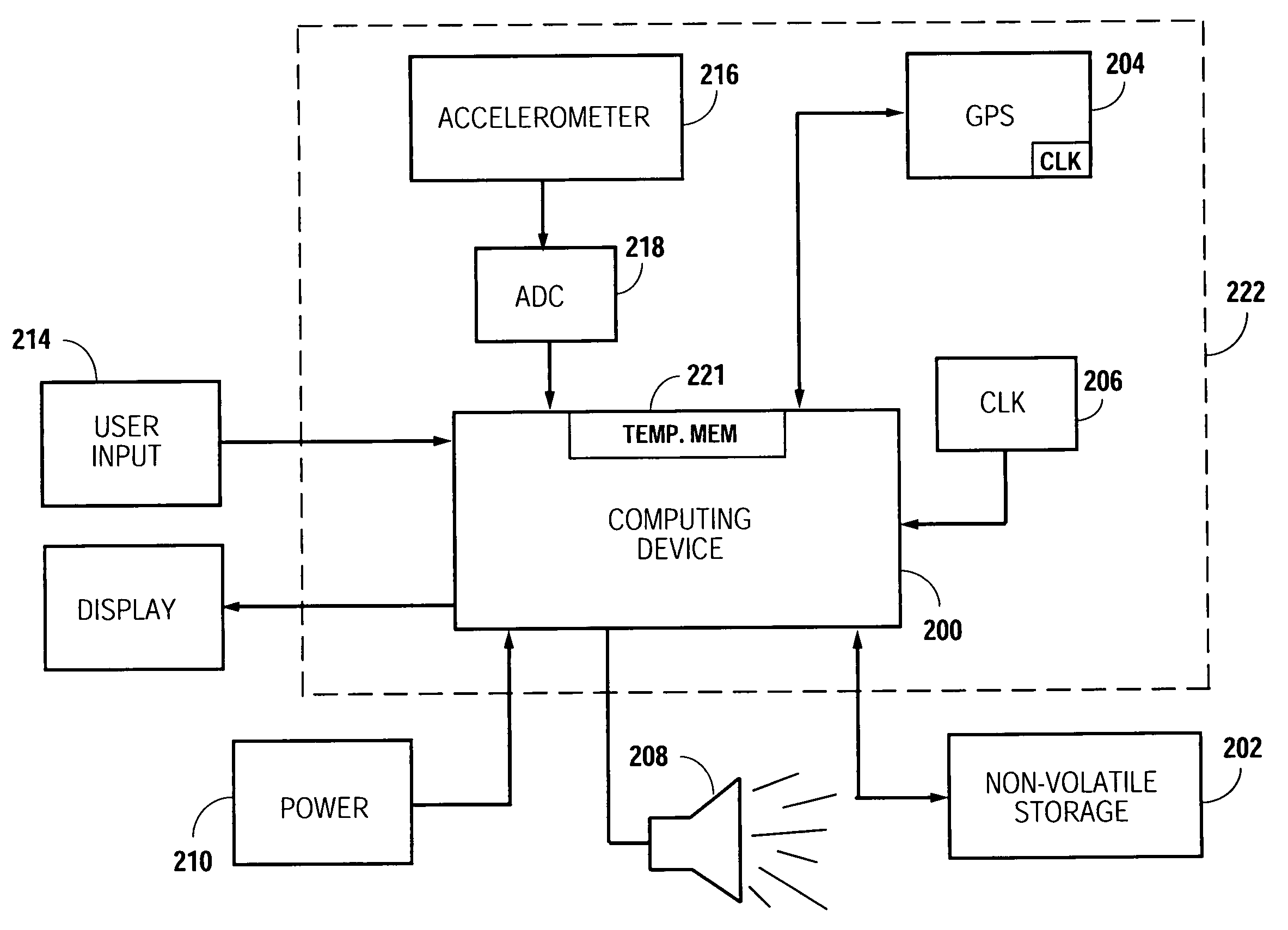
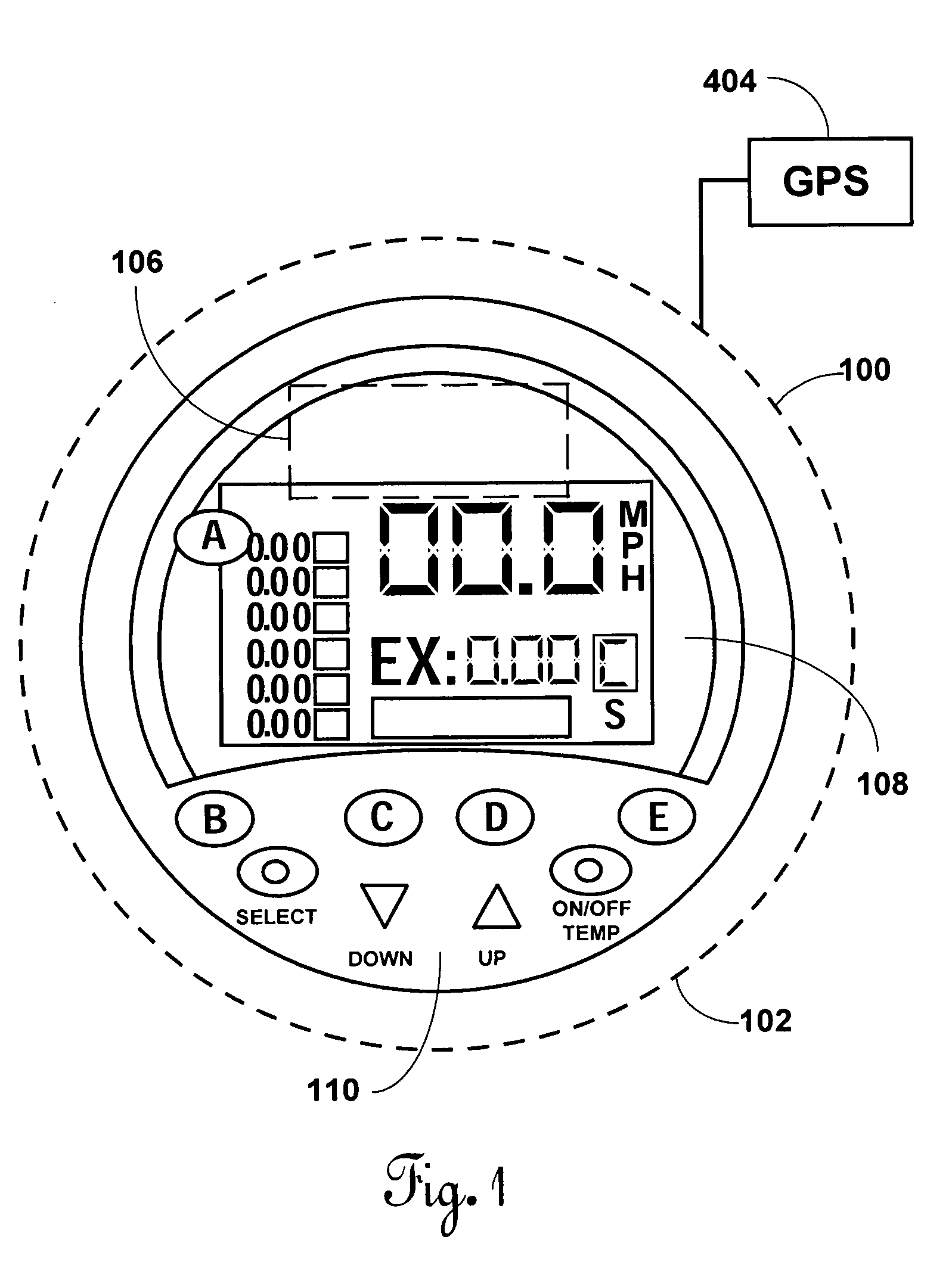
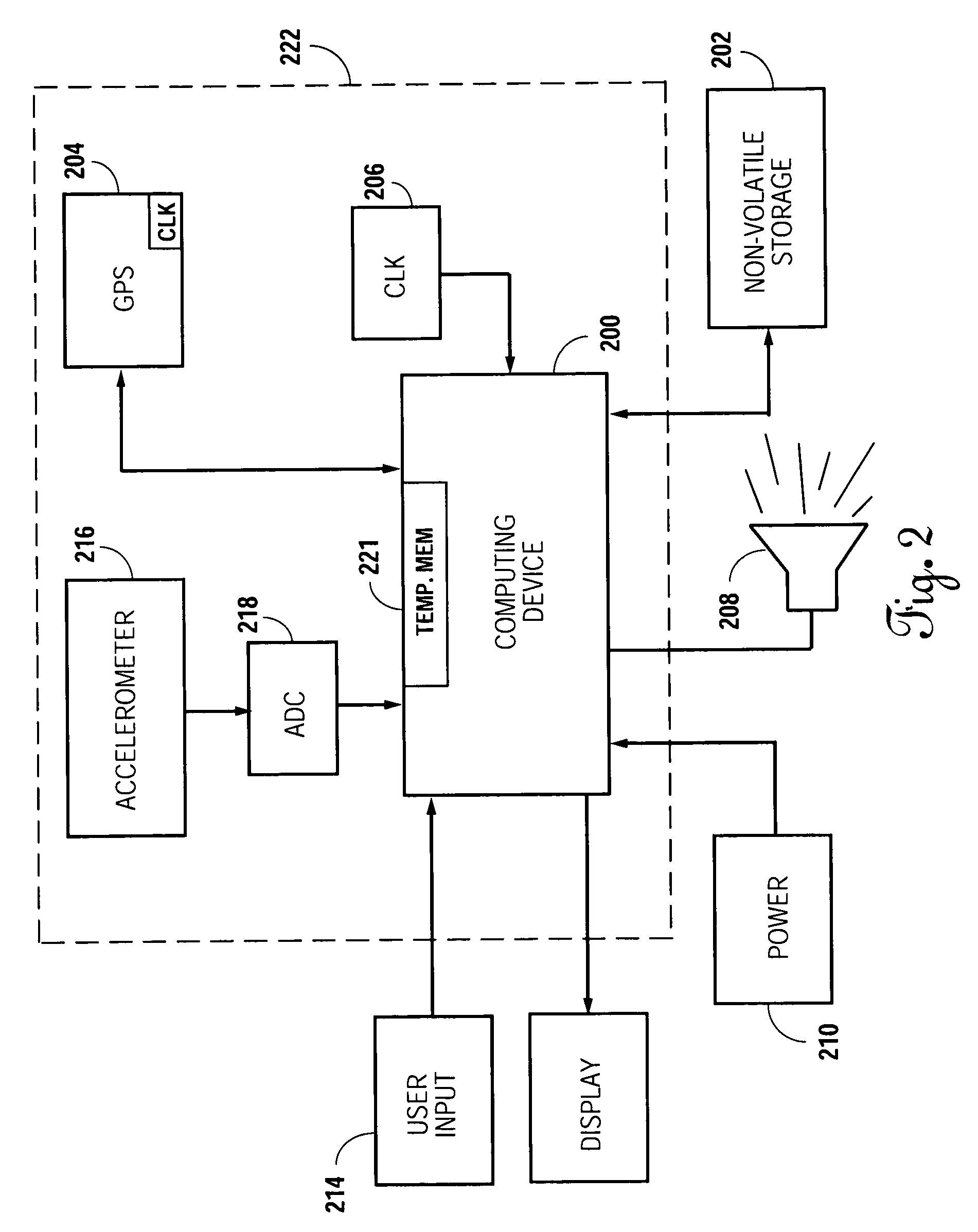
[0016]As show in FIG. 1, the event detector 100 of the present invention includes a housing 102 for housing the electronics of the invent detector an accelerometer 106 and a GPS 104. GPS 104 is preferably a unit separate from housing 102, e.g. a GARMIN® GPS18-5 Hz.

[0017]Electronic housing 102 includes a display 108 and interface buttons 110. As will be appreciated by one skilled in the art the display 108 is preferably made out of moldable materials such as plastic, aluminum, glass, and the like, with a clear glass or plastic cover. Importantly, the housing is adapted to be waterproof to prevent damage to the electronics when in use. The display 108 may be a commercially available LCD display that is capable of displaying numbers or letters and information related to the event. User interface buttons 110 are actuators attached to th...


PUM


Abstract

An automatic timing measurement system that provides a measure of time of passage of a watercraft through a prescribed course. Algorithms based on inertial or other estimates augmented by GPS speed / position measurements are used to track position of a watercraft. Said position estimates are used to allow the locations of prescribed courses to be mapped and memorized. Algorithms are then used to allow the apparatus to automatically detect passage of a watercraft through mapped courses for the purpose of measuring and reporting time of passage of said watercraft past key points in said course, and for modifying the behavior of the speed control portion of the apparatus if necessary at certain points in the mapped course. A measure of accuracy of driver steering can be provided along with the ability to automatically steer the watercraft through the course if “steer-by-wire” mechanism is available. GPS speed control is augmented with a secondary velocity measurement device that measures speed over water resulting in an optional user selectable real-time compensation for water current. Furthermore, GPS is used as the key input to produce boat speed-based pull-up profiles.

Description

[0001]This patent is a continuation-in-part patent application that claims priority and incorporates herein by reference U.S. patent application Ser. No. 11 / 056,848, now issued as U.S. Pat. No. 7,229,330; U.S. patent application Ser. No. 11 / 811,616, filed Jun. 11, 2007; U.S. patent application Ser. No. 11 / 811,605 filed Jun. 11, 2007; U.S. patent application Ser. No. 11 / 611,606, filed Jun. 11, 2007; U.S. patent application Ser. No. 11 / 811,604, filed Jun. 11, 2007; and U.S. patent application Ser. No. 11 / 811,617. filed Jun. 11, 2007.FIELD OF THE INVENTION[0002]The present invention pertains to the field of water sports and boating and more specifically to electronic devices for use in water sports.BACKGROUND OF THE INVENTION[0003]Competitors in trick, jump, and slalom ski and wakeboard events require tow boats capable of consistent and accurate speed control. Successful completion of slalom and jump runs require passes through a competition water course at a precise specific speed. Co...

Claims


Application Information

Patent Timeline
IPC IPC(8): G05D1/00G01C21/00
CPCB63B49/00B63J99/00G05D1/0206Y02T70/742G01C21/00B63J2099/008G01C21/165G01C21/20G01C21/203B63B79/40B63B79/10G01C21/3811G01C21/188B63B34/60G05D1/02G05D1/027G01C23/00G01C21/10G01C21/26Y02T70/00
Inventor WALSER, MICHAEL W.GUGLIELMO, KENNON H.SHOUSE, KENNETH R.GROGAN, JOSEPH
Owner ECONTROLS INC
Learn More