Light-Transmitting Film, Method of Forming Light-Transmitting Film, and Liquid Crystal Display

Active Publication Date: 2008-10-09
SATURN LICENSING LLC
21 Cites 50 Cited by

AI-Extracted Technical Summary

Problems solved by technology

Consequently, there is a problem in that the illumination light from the backlight cannot be used efficiently and luminance cannot be improved.
However, by using such a reflective polarizer, the production cost of the liquid crystal display apparatus increases and the number of components incr...

Method used

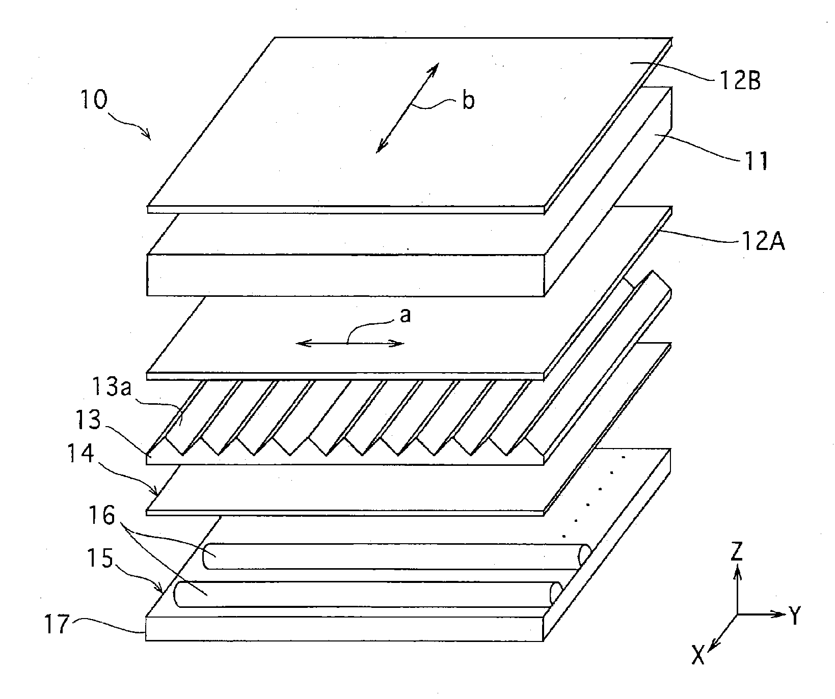
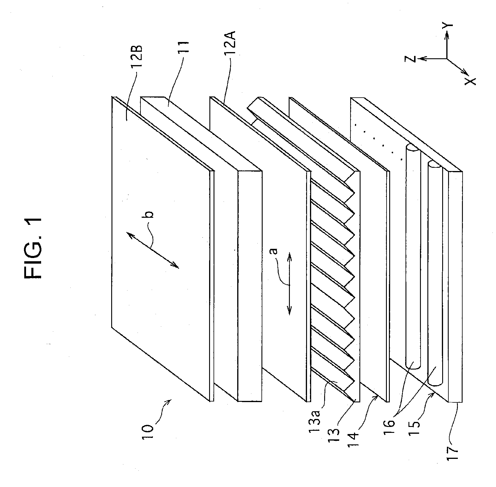
[0043]For example, when the index of refraction of the prism extension direction is greater than the index of refraction of the prism alignment direction, the effect is maximized when the direction of the transmission axis a of light of the first polarizer 12A is set to the prism alignment direction, as shown in FIG. 1. However, when the direction of the transmission axis a and the prism alignment direction cannot be matched due to reasons such as obtaining a suitable angular luminance distribution or improving the contrast ratio of the liquid crystal display panel 11, the angle formed by the transmission axis a and the prism alignment direction may be increased. In such a case, to improve the front luminance, the angle must be between 0° to 45° and more preferably should be between 0° to 20°.
[0044]When the index of refraction of the prism alignment direction is greater than the index of refraction of the prism extension direction, the effect is maximized when the direction of the transmission axis a of the first polarizer 12A is set to the prism extension direction. However, when the direction of the transmission axis a and the prism extension direction cannot be matched due to reasons such as obtaining a suitable angular luminance distribution or improving the contrast ratio of the liquid crystal display panel 11, the angle formed by the transmission axis a and the prism extension direction may be increased. In such a case, to improve the front luminance, the angle must be between 0° to 45° and more preferably should be between 0° to 20°.
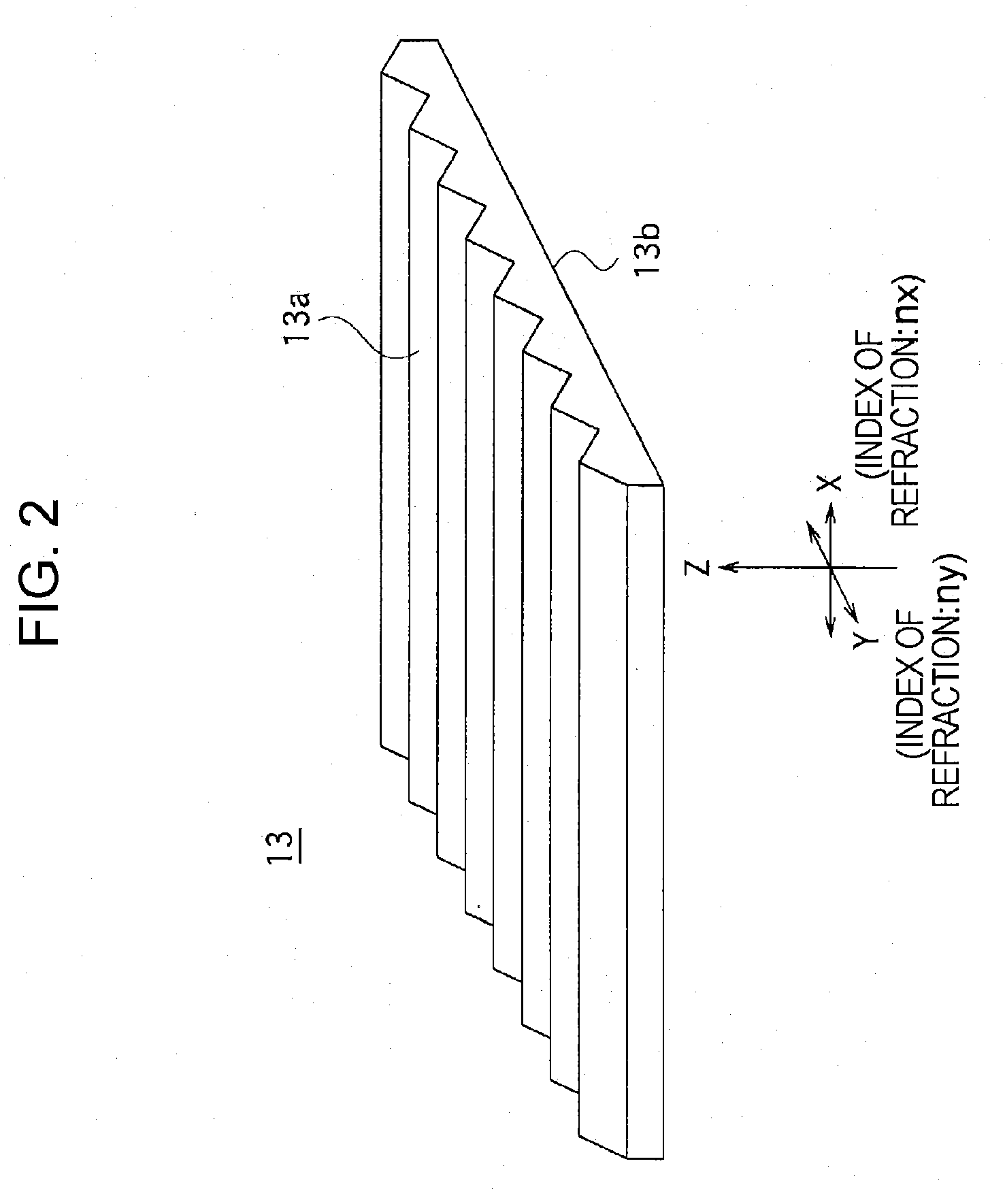
[0045]The prism sheet 13 corresponds to the light-transmitting film according to the present invention and is used as a luminance improvement film for improving the front luminance of the liquid crystal display apparatus 10. The prism sheet 13 is disposed on the light emission side of the diffuser 14 that diffuses and emits illumination light (hereinafter also referred to as “backlight beams”) from the backlight unit 15 and, as described below, has a collecting function and a predetermined polarization split function.
[0054]As described above, by providing in-plane anisotropy to the prism sheet 13, a predetermined polarization split effect can be obtained in addition to the collecting effect of backlight beams. Furthermore, the light reflected at the prism sheet 13 according to the above-described example will be reflected at the surfaces of the reflector 17 (FIG. 1) and the diffuser 14 of the backlight unit 15 and will be incident on the prism sheet 13 again without being polarized. Therefore, light efficiency is increased, and the light can contribute to the improvement of front luminance.
[0060]The stretching direction is set to the prism extension direction so as to suppress a change in the target optical characteristic caused by a change in the prism shape before and after stretching. FIG. 4B illustrates a change in the external shape of the prism structure surface before and after stretching, where the solid line represents before stretching and the single dotted line represents after stretching. By setting the stretching direction to the prism extension direction (X direction), the cross-sectional shape of the prism after stretching is in a substantially scaling relationship with the cross-sectional shape of the prism before stretching. Therefore, change in the optical characteristic can be suppressed, and the desired prism shape can be controlled at high accuracy.
[0067]Part of the backlight beam L reflected at the prism sheet 13 is reflected at the surface of the diffuser 14 or the reflector 17 of the backlight unit 15 and is incident on the prism sheet 13 again. Such ...

Benefits of technology

[0017]By such a structure, the emission light from the light-transmitting film can be efficiently emitted at the liquid crystal display panel. Therefore, the backlight beams can be used efficiently, and the luminance of the liquid crystal display apparatus can be improved.
[0018]As described above, with the light-transmitting film according to the present invention, since the extension direction of the three-dimensiona...

Abstract

A light-transmitting film that has a predetermined polarization split function, in addition to a light-collecting function is provided. The index of refraction nx in a prism extension direction and the index of refraction in a prism alignment direction differ from each other. By generating a difference in the indices of refraction in the prism extension direction and the prism alignment direction orthogonal thereto, for the light incident on the light-transmitting film, the polarization component Lx oscillating in the prism extension direction and the polarization component Ly oscillating in the prism alignment direction can have different transmission characteristics. For example, by setting the index of refraction in the prism extension direction greater than the index of refraction in the prism alignment direction (nx>ny), among the light incident on the light-transmitting film, the amount of return light of the polarization component Lx oscillating in the prism extension direction is greater than that of the polarization component Ly oscillating in the prism alignment direction. In this way, not only a light-collecting function, but also a predetermined polarization split function is obtained.

Application Domain

Technology Topic

Image

  • Light-Transmitting Film, Method of Forming Light-Transmitting Film, and Liquid Crystal Display
  • Light-Transmitting Film, Method of Forming Light-Transmitting Film, and Liquid Crystal Display
  • Light-Transmitting Film, Method of Forming Light-Transmitting Film, and Liquid Crystal Display

Examples

  • Experimental program(6)

Example

First Example
Forming Prism Sheet
[0077]As an original metal embossed plate for hot press for transferring the prism shape to the resin film, a plate was used with surface engraved in a manner such that the cross-section includes right isosceles triangles, with apex angles of 90 degrees, regularly and continuously arranged adjacent and parallel to each other so that the distance between a projecting portion and an adjacent projecting portion and the distance between a concave portion and an adjacent projecting portion are both 50 μm. The resin film was thermoplastic resin, and a 200-μm thick amorphous PET (A-PET) sheet (NovaClear (trademark) SG007 manufactured by Mitsubishi Chemical Corporation, Tg approximately 70° C.) was used. This resin film was hot pressed at 100° C. for 10 minutes at 100 kgf/cm2 (9.8 Mpa), and immediately after pressing, ice water was added to obtain a transparent isotropic prism sheet.
[Stretching Prism Sheet]
[0078]The obtained isotropic prism sheet was cut into an 8 cm long (in the prism extension direction) and 5 cm wide rectangle. Then, the triangular cross-sections (prism cross-sections) at both edges in the longitudinal direction were held with a manual stretching machine, and an anisotropic prism sheet was obtained by carrying out uniaxial stretching at a stretching speed of 1 cm/sec so that the center of the sample is stretched in the stretching by 3.5 times in 55-° C. warm water.
[0079]The triangular cross-sections of the obtained anisotropic prism sheet and the unstretched isotropic prism sheet were measured using a surface roughness meter (Surfcoder ET4001A manufactured by Kosaka Laboratory Ltd.). As a result, both sheets included right isosceles triangles having a 45-degrees base angle that is the same as the original plate. Furthermore, the prism of the sample before stretching was approximately a 50 μm pitch, which is the same as the original plate, whereas the prism sample after stretching was approximately a 30 μm pitch.
[0080]FIG. 8 illustrates a schematic cross-sectional view of the prism sheet after stretching. In the drawing, the chain dotted line represents the cross-sectional shape of the sample before stretching, and the solid line represents the cross-sectional shape of the sample after stretching. It can be noticed that the shapes of the prism are similar before and after stretching.
[0081]The chain double-dotted line represents the shape of the prism after the sample cut into 1.5 cm long and 5 cm wide shapes in the longitudinal direction (prism extension direction). As shown in the example, when a sample having a longitudinal/horizontal ratio less the one is stretched in the longitudinal direction, the cross-sectional shape of the sheet is deformed, and a prism shape similar to the original cannot be obtained. Therefore, it is preferable to cut out the sample so that the longitudinal/horizontal ratio is one or greater.
[Measurement of Birefringence]
[0082]Next, the birefringence of the obtained anisotropic prism sheet was measured. To measure the birefringence, as shown in FIG. 9, polarized light was orthogonally incident on a prism surface of a sheet 45; the transmitted light was detected by a measuring unit 46; and the difference Δn (=nx−ny) of the index of refraction nx in the prism extension direction and the index of refraction ny in the prism alignment direction were calculated on the basis of the difference of the emission angles φ of the transmitted light. In other words, the emission angles φ of the transmitted light differ depending on the incident polarization direction, and, as shown in FIG. 10, the emission angle φx of the polarization component oscillating in a parallel manner in the prism extension direction (hereinafter this is referred to as “vertically polarized light Lx”) is greater than the emission angles φy of the polarization component oscillating in a parallel manner in the prism alignment direction (hereinafter this is referred to as “horizontally polarized light Ly”). By employing this, Δn can be calculated,
[0083]FIG. 11 illustrates the measurement result representing the relationship between the amount of light of the vertically polarized light Lx and the horizontally polarized light Ly transmitted through the sheet 45 and the emission angle. The unit (a.u.) of the vertical axis stands for “arbitrary unit” and is a relative value. As a result of the measurement, as shown in FIG. 12, the index of refraction nx in the prism extension direction of the obtained anisotropic prism sheet 45 is 1.62, whereas the index of refraction ny in the prism alignment direction is 1.55, and Δn is 0.07.
[0084]According to this result, after the shape of the prisms is hot pressed onto the A-PET sheet, by uniaxial stretching, an anisotropic prism sheet having different indices of refraction in the prism extension direction and the alignment direction was obtained. Furthermore, as shown in FIG. 11, it can be confirmed that the transmittance of the horizontally polarized light Ly is greater than that of the vertically polarized light Ly. This is because, since the index of refraction nx in the prism extension direction is greater than the index of refraction ny in the prism alignment direction, the total reflection effect of the inclined surface of the prism on the polarization component Lx parallel to the prism extension direction is increased and the amount of light transmitted is reduced compared with Ly.
[Luminance Alignment Evaluation]
[0085]Next, the luminance alignment of the anisotropic prism sheet 45 according to this example was measured. As shown in FIG. 13, the backlight unit is an edge light type including a light source 50, a reflector 51, and a light-guiding plate 52. A diffuser 53, a luminance-improvement film 54, an anisotropic prism sheet 45, and a polarizer 55 are stacked on the light-guiding plate 52 in the respective order. The front luminance and the illuminance were measured using a luminance colorimeter (EZ-contrastXL88 manufactured by ELDIM).
[0086]An isotropic prism sheet (for example, BEF (trademark) manufactured by 3M Company) was used as the luminance-improvement film 54, and the prism extension direction was disposed in the left and right direction in the drawing (horizontal direction). The anisotropic prism sheet 45 was disposed with the prism extension direction in the up and down direction in the drawing (vertical direction), and the prism extension direction was disposed orthogonal to the luminance-improvement film 54. Two polarizers 55 were provided: one having a light-transmission axis A in the vertical direction: and the other having a light-transmission axis B in the horizontal direction. Both polarizers 55 were used to measure the luminance alignment of the vertically polarized light and the horizontally polarized light.

Example

First Comparative Example
[0087]The same method was applied to measure the front luminance and the illuminance as that of the first example, except that, instead of the anisotropic prism sheet 45, a unstretched anisotropic prism sheet (90 degrees prism apex angle and 50 μm pitch) was used.
[0088]The measurement results are shown in Table 1 and FIG. 14.
TABLE 1 First Example Change rate Front (example/comparative luminance (cd/m2) Illuminance (lux) example) 1st 1st 1st 1st comparative 1st comparative 1st comparative example example example example example example Horizontally 667 622 626 532 107% 118% polarized light Vertically 579 627 501 562 92% 89% polarized light
[0089]According to the results shown in Table 1 and FIG. 14, both the front luminance and the illuminance of the vertically polarized light of the anisotropic prism sheet according to this example were decreased compared with the anisotropic prism sheet according to the first comparative example. However, the luminance and the illuminance of the horizontally polarized light were increased compared with the anisotropic prism sheet according to the first comparative example.
[0090]According to the results described above, with the anisotropic prism sheet, since a larger amount of vertically polarized light is reflected at the prism surface and is recycled as light in all directions by the diffuser and the reflector, it contributes to an increase in the luminance and illuminance of the horizontally polarized light. Therefore, by setting the transmission axis of the polarizer 55 in the direction of the horizontally polarized light, i.e., the prism alignment direction of the anisotropic prism sheet 45, light can be efficiently used and the front luminance and the illuminance (light extraction efficiency) can be improved.

Example

Second Example
Forming Prism Sheet
[0091]As an original metal embossed plate for hot press for transferring the prism shape to the resin film, a plate was used with surface engraved in a manner such that the cross-section includes right isosceles triangles, with apex angles of 90 degrees, regularly and continuously arranged adjacent and parallel to each other so that the distance between a projecting portion and an adjacent projecting portion and the distance between a concave portion and an adjacent projecting portion are both 50 μm. The resin film was thermoplastic resin, and a 200-μm thick amorphous PEN (A-PEN) sheet (Tg approximately 120° C.) was used. This resin film was hot pressed at 150° C. for 10 minutes at 100 kgf/cm2 (9.8 Mpa), and immediately after pressing, ice water was added to obtain a transparent isotropic prism sheet.
[Stretching Prism Sheet]
[0092]The obtained isotropic prism sheet was cut into an 8 cm long (in the prism extension direction) and 5 cm wide rectangle. Then, the triangular cross-sections (prism cross-sections) at both edges in the longitudinal direction were held with a manual stretching machine, and an anisotropic prism sheet was obtained by carrying out uniaxial stretching at a stretching speed of 1 cm/sec so that the center of the sample is stretched in the stretching by 3.5 times in an environment of 140° C.
[0093]The triangular cross-sections of the obtained anisotropic prism sheet and the unstretched isotropic prism sheet were measured using a surface roughness meter (Surfcoder ET4001A manufactured by Kosaka Laboratory Ltd.). As a result, both sheets included right isosceles triangles having a 45-degrees base angle that is the same as the original plate. Furthermore, the prism of the sample before stretching was approximately a 50 μm pitch, which is the same as the original plate, whereas the prism sample after stretching was approximately a 30 μm pitch.
[0094]FIG. 15 illustrates a schematic cross-sectional view of the prism sheet after stretching. In the drawing, the chain dotted line represents the cross-sectional shape of the sample before stretching, and the solid line represents the cross-sectional shape of the sample after stretching. It can be noticed that the shapes of the prism are similar before and after stretching.
[0095]Next, the birefringence of the obtained anisotropic prism sheet was measured. The birefringence was measured in the same way as in the first example.
[0096]FIG. 16 illustrates the measurement result representing the relationship between the amount of light of the vertically polarized light Lx and the horizontally polarized light Ly transmitted through the anisotropic prism sheet and the emission angle. The unit (a.u.) of the vertical axis stands for “arbitrary unit” and is a relative value. As a result of the measurement, as shown in FIG. 17, the index of refraction nx in the prism extension direction of the obtained anisotropic prism sheet is 1.79, whereas the index of refraction ny in the prism alignment direction is 1.56, and Δn is 0.23.
[0097]According to this result, after the shape of the prisms is hot pressed onto the A-PEN sheet, by uniaxial stretching, an anisotropic prism sheet having different indices of refraction in the prism extension direction and the alignment direction was obtained. Furthermore, as shown in FIG. 16, it can be confirmed that the transmittance of the horizontally polarized light Ly is greater than that of the vertically polarized light Ly. This is because, since the index of refraction nx in the prism extension direction is greater than the index of refraction ny in the prism alignment direction, the total reflection effect of the inclined surface of the prism on the polarization component Lx parallel to the prism extension direction is increased and the amount of light transmitted is reduced compared with Ly.
[Luminance Alignment Evaluation]
[0098]Next, the luminance alignment of the anisotropic prism sheet according to this example was measured. As shown in FIG. 13, the backlight unit is an edge light type including a light source 50, a reflector 51, and a light-guiding plate 52. A diffuser 53, a luminance-improvement film 54, an anisotropic prism sheet 45, and a polarizer 55 are stacked on the light-guiding plate 52 in the respective order. The front luminance and the illuminance was measured using a luminance calorimeter (EZ-contrastXL88 manufactured by ELDIM).
[0099]An isotropic prism sheet (for example, BEF (trademark) manufactured by 3M Company) was used as the luminance-improvement film 54, and the prism extension direction was disposed in the left and right direction in the drawing (horizontal direction). The anisotropic prism sheet 45 was disposed with the prism extension direction in the up and down direction in the drawing (vertical direction), and the prism extension direction was disposed orthogonal to the luminance-improvement film 54. Two polarizers 55 were provided: one having a light-transmission axis A in the vertical direction: and the other having a light-transmission axis B in the horizontal direction. Both polarizers 55 were used to measure the luminance alignment of the vertically polarized light and the horizontally polarized light.

PUM

no PUM

Description & Claims & Application Information

We can also present the details of the Description, Claims and Application information to help users get a comprehensive understanding of the technical details of the patent, such as background art, summary of invention, brief description of drawings, description of embodiments, and other original content. On the other hand, users can also determine the specific scope of protection of the technology through the list of claims; as well as understand the changes in the life cycle of the technology with the presentation of the patent timeline. Login to view more.

Similar technology patents

LED module and LED lamp including the same

ActiveUS20190326480A1Excellent processabilityImprove luminanceElectroluminescent light sourcesSolid-state devicesEngineeringWavelength conversion
Owner:SAMSUNG ELECTRONICS CO LTD

Backlight unit

InactiveUS20070002584A1Improve luminanceIncadescent screens/filtersElectric discharge tubesPhysicsFluorescent materials
Owner:LG DISPLAY CO LTD

Classification and recommendation of technical efficacy words

  • Efficiently emit
  • Improve luminance
Why Eureka
Try Eureka