Jet pump apparatus

a technology of jet pumps and mixing chambers, which is applied in the direction of mixing methods, mixing machines, and using liquid separation agents, etc., can solve the problems of insufficient space for a jet pump with a sufficiently long mixing chamber, placing constraints on the design of jet pumps,

Inactive Publication Date: 2008-10-09
HONEYWELL NORMALAIR GARRETT HLDG
View PDF11 Cites 15 Cited by
  • Summary
  • Abstract
  • Description
  • Claims
  • Application Information

AI Technical Summary

Benefits of technology

[0009]The invention enables a jet pump apparatus to be provided with a plurality of parallel mixing chambers, each mixing chamber having the preferred mixing chamber length to mixing chamber cross section ratio, whilst overall the jet pump apparatus may be significantly shorter than a compa

Problems solved by technology

Achieving this ratio whilst delivering a desired temperature of gas downstream thus places constraints on jet pump design.
Par

Method used


Image

  • Jet pump apparatus
  • Jet pump apparatus
  • Jet pump apparatus

Examples


Embodiment Construction

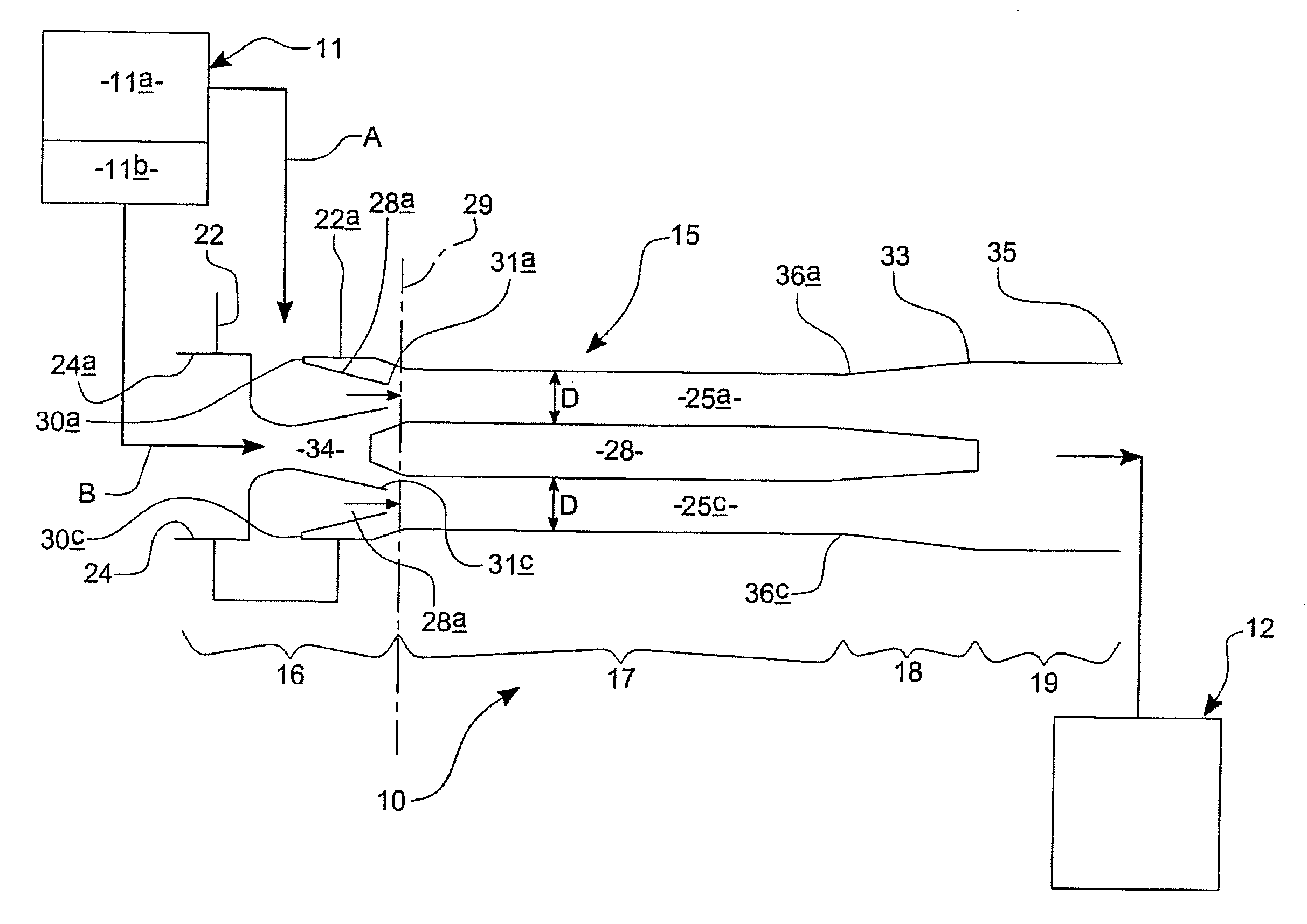
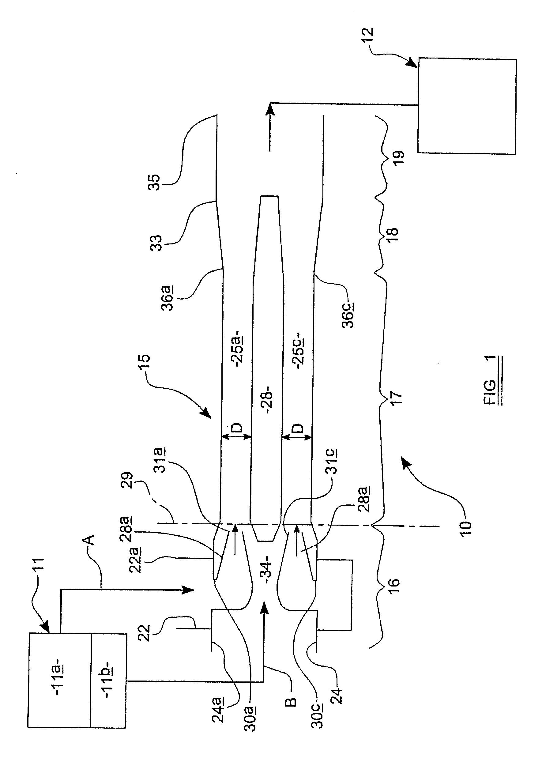
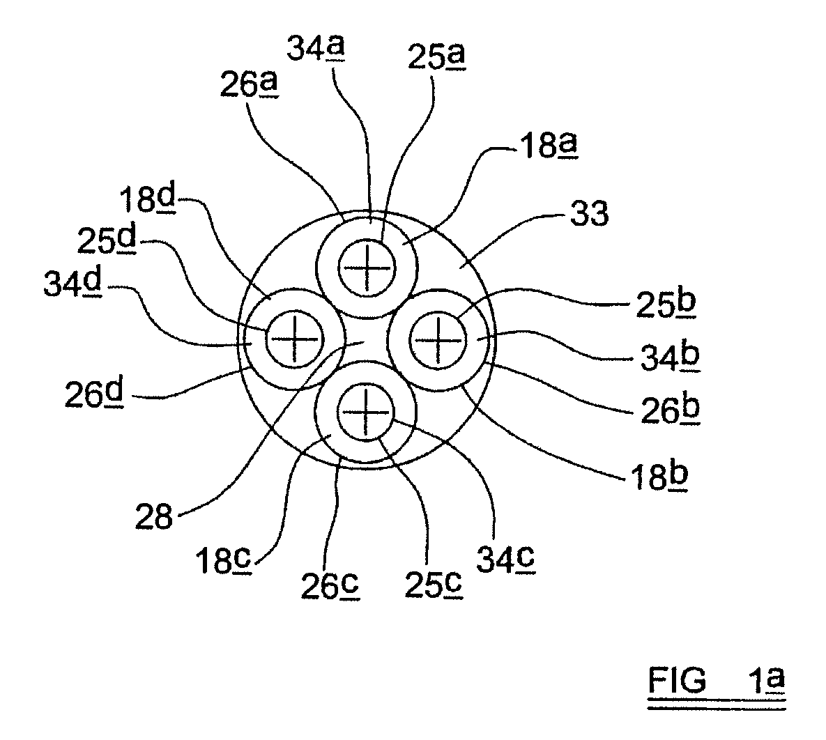
[0023]Referring to FIGS. 1 and 1a and 3 of the drawings there is shown a compressed air supply system 10 of an aircraft 100, the system 10 receiving compressed bleed air from a gas turbine engine 11, and delivering pressurised gas to a downstream gas using apparatus 12 such as for examples only, an on-board oxygen or other product gas generating apparatus 12, which separates the pressurised gas into product gas and non-product gas, and / or an air conditioning apparatus of the aircraft 100.

[0024]The compressed air supply system 10 includes a jet pump apparatus 15 which has an inlet section 16, a mixing section 17, a diffuser section 18 and an outlet section 19.

[0025]The inlet section 16 includes a higher pressure air inlet 22a which is connected to a higher compression stage 11a of the gas turbine engine 11, and a lower pressure air inlet 24a which is connected to a lower compression stage 11b of the gas turbine engine 11.

[0026]The mixing section 17 is provided by a plurality of mixin...


PUM

PropertyMeasurementUnit
Pressureaaaaaaaaaa
Diameteraaaaaaaaaa
Lengthaaaaaaaaaa

Abstract

A jet pump apparatus for mixing a higher pressure gas from a higher pressure gas supply and a lower pressure gas from a lower pressure gas supply, includes an inlet section, an outlet section, a diffuser section and a mixing section, the inlet section including a higher pressure gas inlet and a lower pressure gas inlet, the mixing section including a plurality of separated mixing chambers, and the diffuser section including diffusers for receiving mixed gases from each of the mixing chambers, and the outlet section receiving mixed gases from the diffuser section and conveying the mixed gases to a mixed gas outlet, and the inlet section including a higher pressure gas inlet duct which receives higher pressure gas from the higher pressure gas inlet, and a lower pressure gas inlet duct which receives lower pressure gas from the lower pressure gas inlet, and for each of the plurality of mixing chambers, there being a primary nozzle for introducing primarily higher pressure gas from the higher pressure gas inlet duct to a respective mixing chamber, and there being a secondary inlet for introducing primarily lower pressure gas from the lower pressure inlet duct to each of the mixing chambers, the higher pressure gas being derived from a compressor section of a gas turbine engine.

Description

CROSS-REFERENCE TO RELATED APPLICATIONS[0001]This application claims priority to United Kingdom Patent Application No. GB0705361.4 filed Mar. 21, 2007, which is incorporated in its entirety by reference herein.BACKGROUND OF THE INVENTION[0002]This invention relates to a jet pump apparatus for mixing a higher pressure gas from a higher pressure gas supply derived from a compressor stage of a gas turbine engine, which typically is an aircraft engine, and a lower pressure gas from a lower pressure gas supply in order to provide a pressurised gas supply to a downstream apparatus, such as for example only, a downstream on-board oxygen generating system, e.g. of the kind which utilises molecular sieve bed technology, or an air conditioning apparatus, or any other desired gas-using downstream apparatus.[0003]More particularly but not exclusively the invention is for mixing higher and lower pressure gases which are produced by respective higher and lower compression stages of a gas turbine ...

Claims


Application Information

Patent Timeline
IPC IPC(8): F04F5/00B01F3/02B01F23/10
CPCB01F3/02B01F5/0418B01F5/0421F04F5/18B64D13/00F04F5/466B01F5/0428B01F23/10B01F25/31232B01F25/31242F04F5/16B01F25/3123
Inventor SAMPSON, BERNARD FRANCISHARVEY, ROBERT JOHN
Owner HONEYWELL NORMALAIR GARRETT HLDG
Why Eureka
Try Eureka